Wiring
3.4.3 Control Signal Functions
3 -28
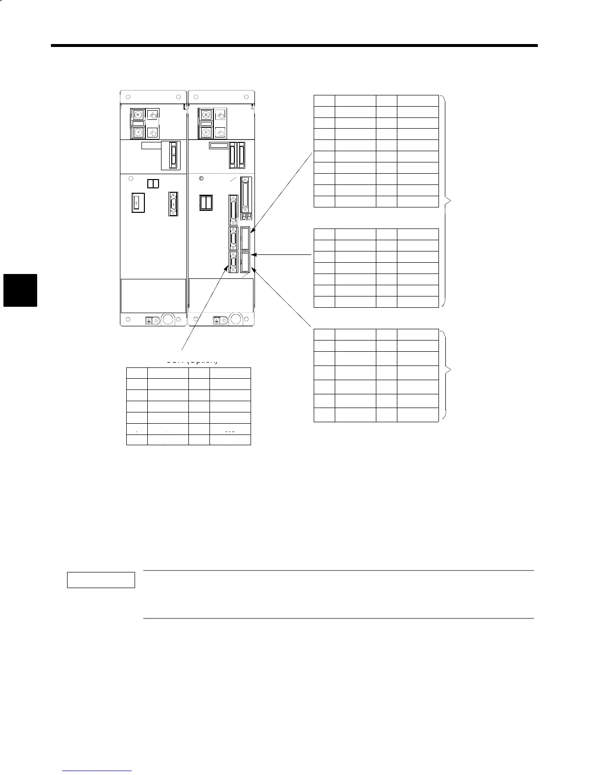
8CN (Option)
20 SS 10 —
P
P
19 *SPB 9 CPA
+
+
18 SPB 8 *CPC
N
N
−
−
17 *SPA 7 CPC
5CN
51CN/52CN
16 SPA 6 +5V
15 *SPC 5 +5V
14 SPC 4 +5V
CHARGE
CHARGE
4CN
6CN
13 *CPB 3 0V
88
12 CPB 2 0V
P1
P1
1CN
11 *CPA 1 0V
Encoder Method Orientation
N1
N1
ar
1CN
8CN
9CN (Option)
2CN
14 — 7 *SPBO
13 — 6 SPBO
3CN
12 — 5 *SPAO
11 — 4 SPAO
9CN
10CN
10 — 3 *SPCO
9 — 2 SPCO
8 — 1 SS
10CN (Option)
Converter Inverter
14 SIG− 7 —
13 SIG+ 6 —
3CN (Option)
12 +15V 5 0V
14 7
—
+5V
11 — 4 —
Magnetic Sensor Method
Orientation Card
13
6
—
OP1
10 +12V 3 0V
12
5
—
0V
9 — 2 —
10
4
3
—
+5V
0V
RX
8
— 1 SS
9
2
+5V
TX
8
1
OP2 0 V
Note: Terminal arrangement is as when the connectors on the PC board are viewed from the front of the unit.
Fig 3.19 Terminal Arrangements of Control Signal Connectors (Optional)
3.4.3 Control Signal Functions
The following table outlines the functions of the control circuit signals. Use appropriate signals according
to the purpose.
The12-bit digital reference signals to 1CN-19 through 1CN-30 and the sequence input signals to 6CN-5
through 6CN-18 can be 0 V, 24 V, or external common signals. The wiring of terminals varies with the input
method. Refer to 3.4.4 Sequence Input Signal Circuits for details.
3
IMPORTANT