Control Signals
4 -20
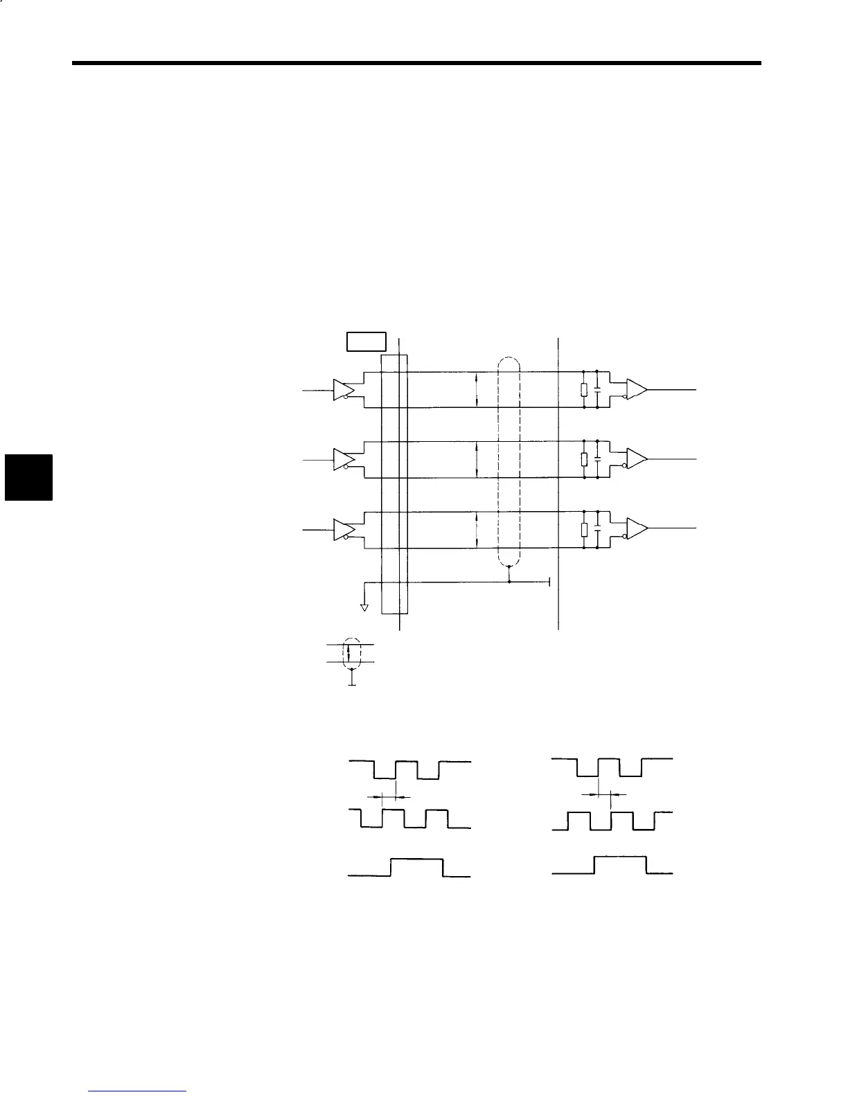
4.7 Encoder Pulse Output Circuit
Phase A, B, and C (origin) signals are output from the motor encoder.
An asterisk indicates a reversed signal.
The output signals have the following specifications and can be used for position feedback.
J
Signal Configuration
90
°
phase-difference, two-phase pulse (A and B), and marker pulse (C)
J
Output Circuit Configuration
The output circuit is a line receiver with RS-422A specifications. Use a line receiver with specifications
matching the RS-422A specifications for signal exchange as shown in the following connection example.
Phase A
Phase B
Phase C
Output line driver
SN75174
Receiver circuit (prepared by user)
Phase A
Phase B
Phase C
Use a line receiver matching
EIA RS-422A standards,
such as the SN75175.
indicates shielded twisted-pair wires.
13
14
15
16
11
12
17
P
P
P
P
Inverter
R
T
R
T
R
T
C
T
C
T
C
T
R
T
:
51 to 200Ω
C
T:
47 to 200
P
F
PAO
*PAO
PBO
*PBO
PCO
*PCO
1CN
Fig 4.5 Encoder Pulse Output Circuit
J
Output Phase
Phase A
(PAO)
Phase B
(PBO)
Phase C
(PCO)
Phase A
(PAO)
Phase B
(PBO)
Phase C
(PCO)
(a) Forward
(b) Reverse
90°
90°
Fig 4.6 Output Phase
4