Specifications
14.3.1 AC Reactor
14 -42
14.3 Options and Peripheral Units
This section explains the specifications for the options and peripheral units.
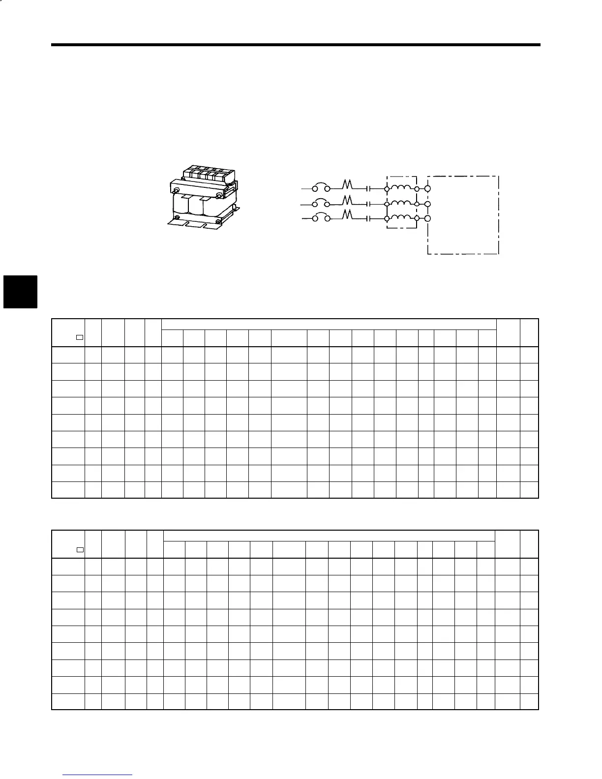
14.3.1 AC Reactor
The exterior of the AC Reactor (UZBA-B: Input, 50/60 Hz) and connections examples are shown below.
Connection Example
MCCB
Magnetic
contactor
AC Reactor
Converter
VS-656MR5
U
X
V
Y
W
Z
R/L1
S/L2
T/L3
J
With Terminal Block
Select an AC reactor from the table below according to Converter (VS-656MR5) model.
200 V Class
Model Cur - Induc-
Dimensions in mm (inches)
Approx. Heat
CIMR-
MR5
V
:
rent
A
-
tance
mH
Code
No.
Fig.
No.
A
(Max.)
A1 B
B1
(Max.)
B2 C1 C2 D E F I J K L M
.
Mass
kg (lb)
Loss
W
23P7 20 0.53
X010
057
1
130
(5.12)
—
88
(3.46)
60
(2.36)
44
(1.73)
105±5
(4.13±0.2)
25
(0.98)
50
(1.97)
70
(2.76)
130
(5.12)
3.2
(0.13)
M6
9
(0.35)
7
(0.28)
M4
3
(6.6)
35
25P5 30 0.35
X010
058
1
130
(5.12)
—
88
(3.46)
60
(2.36)
44
(1.73)
105±5
(4.13±0.2)
40
(1.57)
50
(1.97)
70
(2.76)
130
(5.12)
3.2
(0.13)
M6
9
(0.35)
7
(0.28)
M5
3
(6.6)
45
27P5 40 0.265
X010
059
2
130
(5.12)
150
(5.91)
98
(3.86)
65
(2.56)
49
(1.93)
105±5
(4.13±0.2)
40
(1.57)
50
(1.97)
80
(3.15)
130
(5.12)
3.2
(0.13)
M6
9
(0.35)
7
(0.28)
M6
4
(8.8)
50
2011 60 0.18
X010
060
1
160
(6.3)
—
105
(4.13)
75
(2.95)
52.5
(2.07)
130±5
(5.12±0.2)
40
(1.57)
75
(2.95)
85
(3.35)
160
(6.3)
2.3
(0.09)
M6
10
(0.39)
7
(0.28)
M6
6
(13.2)
65
2015 80 0.13
X010
061
1
180
(7.09)
—
100
(3.94)
85
(3.35)
50
(1.97)
150±5
(5.91±0.2)
42
(1.65)
75
(2.95)
80
(3.15)
180
(7.09)
2.3
(0.09)
M6
10
(0.39)
7
(0.28)
M6
8
(17.6)
75
2018 90 0.12
X010
062
2
180
(7.09)
190
(7.48)
100
(3.94)
90
(3.54)
50
(1.97)
150±5
(5.91±0.2)
45
(1.77)
75
(2.95)
80
(3.15)
180
(7.09)
2.3
(0.09)
M6
10
(0.39)
7
(0.28)
M8
8
(17.6)
90
2022 120 0.09
X010
063
2
180
(7.09)
190
(7.48)
100
(3.94)
95
(3.74)
50
(1.97)
150±5
(5.91±0.2)
45
(1.77)
75
(2.95)
80
(3.15)
180
(7.09)
2.3
(0.09)
M6
10
(0.39)
7
(0.28)
M8
8
(17.6)
90
2030 160 0.07
X010
064
3
210
(8.27)
—
100
(3.94)
210
(8.27)
—
175±5
(6.89±0.2)
110
(4.33)
75
(2.95)
80
(3.15)
205
(8.07)
2.3
(0.09)
M6
10
(0.39)
7
(0.28)
M10
12
(26.5)
100
2037 200 0.05
X010
120
3
210
(8.27)
—
116
(4.57)
230
(9.06)
—
175±5
(6.89±0.2)
130
(5.12)
75
(2.95)
95
(3.74)
205
(8.07)
2.3
(0.09)
M6
10
(0.39)
7
(0.28)
M10
15
(0.59)
110
400 V Class
Model Cur - Induc-
Dimensions in mm (inches)
Approx. Heat
CIMR-
MR5V
:
rent
A
-
tance
mH
Code
No.
Fig.
No.
A
(Max.)
A1 B
B1
(Max.)
B2 C1 C2 D E F I J K L M
.
Mass
kg (lb)
Loss
W
45P5 15 1.42
X002
501
1
130
(5.12)
—
98
(3.86)
—
49
(1.93)
105±5
(4.13±0.2)
25
(0.98)
50
(1.97)
80
(3.15)
130
(5.12)
3.2
(0.13)
M6
9
(0.35)
7
(0.28)
M4
4
(8.8)
50
47P5 20 1.06
X010
099
1
160
(6.3)
—
90
(3.54)
50
(1.97)
45
(1.77)
130±5
(5.12±0.2)
25
(0.98)
75
(2.95)
70
(2.76)
160
(6.3)
2.3
(0.09)
M6
10
(0.39)
7
(0.28)
M4
5
(11)
50
4011 30 0.7
X010
100
1
160
(6.3)
—
105
(4.13)
95
(3.74)
52.5
(2.07)
130±5
(5.12±0.2)
40
(1.57)
75
(2.95)
85
(3.35)
160
(6.3)
2.3
(0.09)
M6
10
(0.39)
7
(0.28)
M5
6
(13.2)
65
4015 40 0.53
X010
101
1
180
(7.09)
—
100
(3.94)
85
(3.35)
50
(1.97)
150±5
(5.91±0.2)
40
(1.57)
75
(2.95)
80
(3.15)
180
(7.09)
2.3
(0.09)
M6
10
(0.39)
7
(0.28)
M6
8
(17.6)
90
4018 50 0.42
X010
102
1
180
(7.09)
—
100
(3.94)
85
(3.35)
50
(1.97)
150±5
(5.91±0.2)
40
(1.57)
75
(2.95)
80
(3.15)
180
(7.09)
2.3
(0.09)
M6
10
(0.39)
7
(0.28)
M6
8
(17.6)
90
4022 60 0.36
X010
103
1
180
(7.09)
—
100
(3.94)
85
(3.35)
50
(1.97)
150±5
(5.91±0.2)
40
(1.57)
75
(2.95)
80
(3.15)
180
(7.09)
2.3
(0.09)
M6
10
(0.39)
7
(0.28)
M6
8
(17.6)
90
4030 80 0.26
X010
104
1
210
(8.23)
—
100
(3.94)
90
(3.54)
50
(1.97)
175±5
(6.89±0.2)
45
(1.77)
75
(2.95)
80
(3.15)
205
(8.07)
3.2
(0.13)
M6
10
(0.39)
7
(0.28)
M6
12
(26.5)
95
4037 90 0.24
X010
105
1
210
(8.23)
—
116
(4.57)
110
(4.33)
58
(2.28)
175±5
(6.89±0.2)
48
(1.89)
75
(2.95)
95
(3.74)
205
(8.07)
3.2
(0.13)
M6
10
(0.39)
7
(0.28)
M8
15
(33.1)
110
4045 120 0.18
X010
106
1
240
(9.41)
—
126
(4.96)
120
(4.72)
63
(2.48)
205±5
(8.07±0.2)
48
(1.89)
150
(5.90)
110
(4.33)
240
(9.45)
3.2
(0.13)
M8
8
(0.31)
10
(0.39)
M8
23
(50.7)
130
* A: For stand-alone drive system N: for NC system
14
 Loading...


