14.2 Standard Motor Specifications
14 -39
14.2.8 Encoder Connector
The terminal arrangement and dimensions of the encoder connector are given below.
J
Terminal Arrangement
1
234
56
78
9
10 11
12
EL Connector (ELR-12V)
Number
Name Number Name
1
5V
7
PC
2
0V
8
:
PC
3
PA
9
FG (Frame Ground)
4
:
PA
10
SS (Shield)
5
PB
11
TS
6
:
PB
12
Notes:1. Pins 11 and 12 are thermistor signal wires from the motor unit.
2. The asterisk (
:
) before PA, PB, and PC indicate reverse rotation signals.
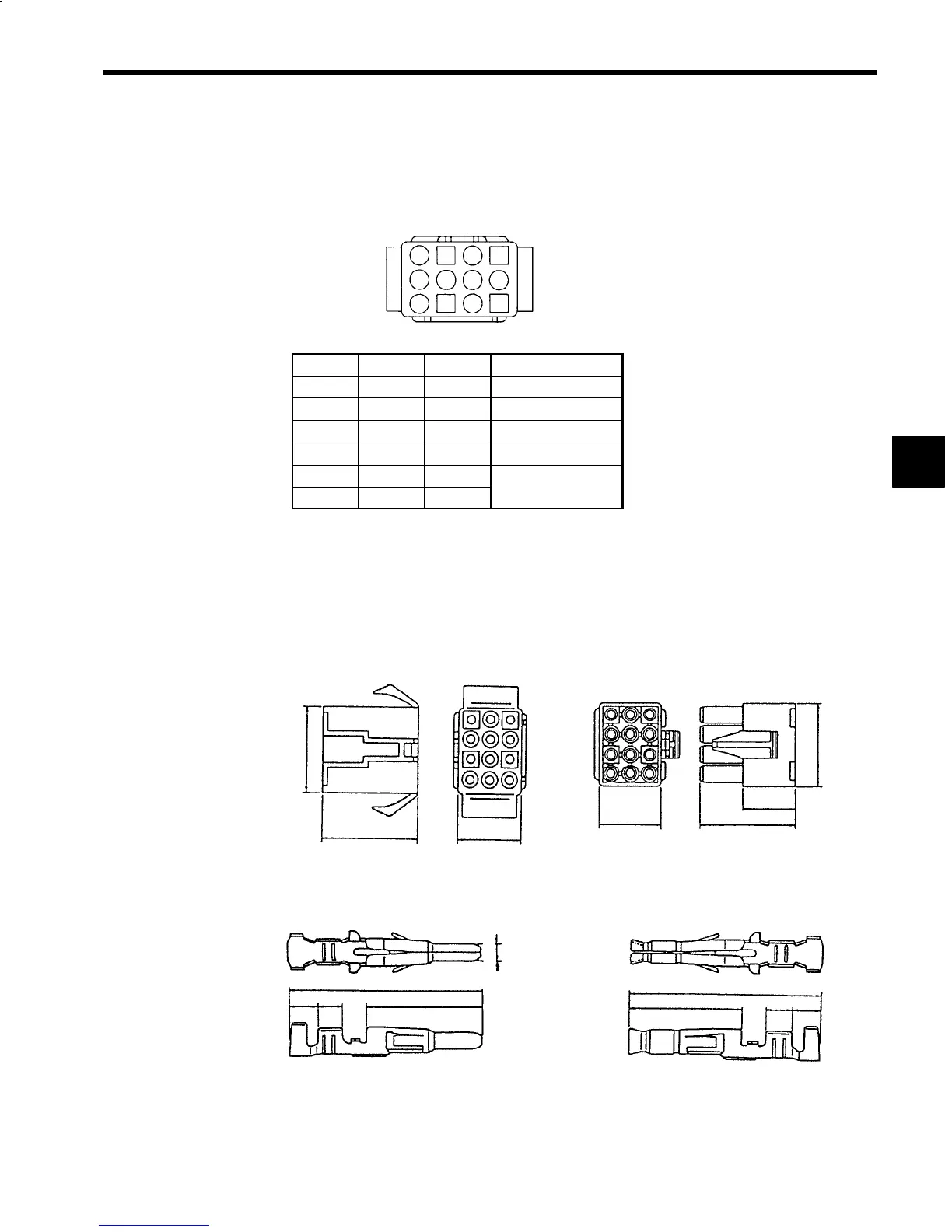
Fig 14.13 Encoder Signal Connector Terminal Arrangement
J
Dimensions
Receptacle housing: ELR-12V
24.6
14.8
Plug housing: ELP-12V
24.6
14.8
14.6
Pin contacts
LLM-01T-1.3E × 11 pins (pins 1 to 9, 11, and 12)
LLM-41T-1.3E × 1 pin (pin 10)
17.7
2.3 2.0
11.3
1.3
Socket contacts
LLF-01T-1.3E × 11 pins (pins 1 to 9, 11, and 12)
LLF-41T-1.3E × 1 pin (pin 10)
17.7
2.3
2.0
11.3
Motor (Wiring Completed)
Cable (Included with Motor Terminal Box)
19.3
19.3
φ
Notes:1. Manufacturer: JST Manufacturing Co., Ltd.
2. The cable connector housing and socket contact is built into the motor. Special tool:
YC-202 and YC-203. (manufactured by JST Manufacturing Co., Ltd.)
Fig 14.14 Encoder Signal Connector Dimensions
14