4.6 Encoder Pulse Input Circuit
4 -19
4.6 Encoder Pulse Input Circuit
Phase A, B, and C (origin) signals [PA, *PA, PB, *PB, PC, *PC] are input into the 2CN connector from the 1024
P/R motor encoder.
An asterisk indicates a reversed signal. The input signals have the following specifications.
J
Signal Configuration
90
°
phase-difference, two-phase pulse (A and B), and marker pulse (C)
J
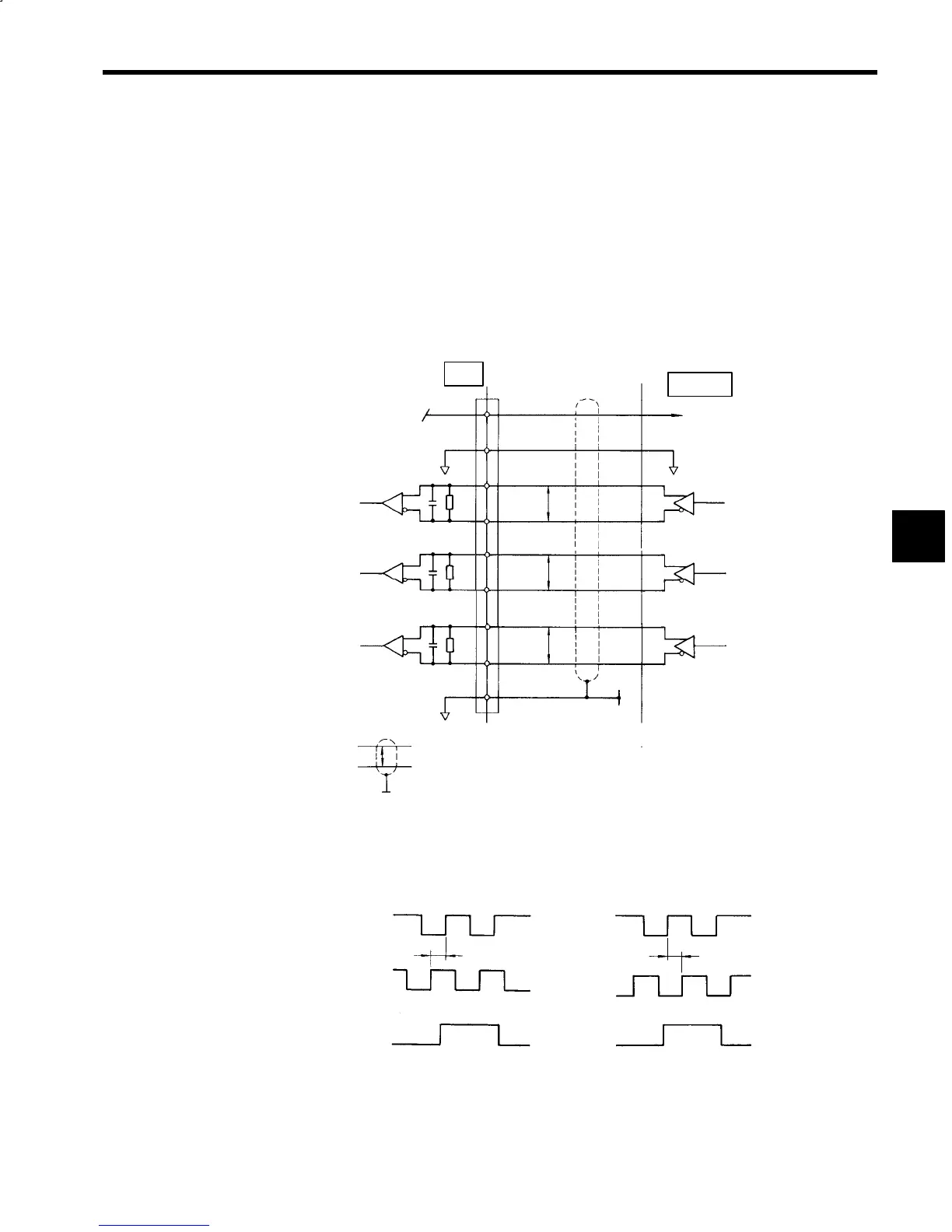
Input Circuit Configuration
The input circuit is a line receiver with RS-422-A specifications.
Inverter
Line receiver
equivalent to
SN75175
Output line driver
equivalent to
SN75174
Encoder
Phase A
Phase B
Phase C
2CN
4, 5, 6
1, 2, 3
16
17
18
19
14
15
+5 V
(300 mA max)
7
SS
P
P
P
+5 V
0V
CR
CR
CR
PA
*PA
PB
*PB
PC
*PC
Phase A
Phase B
Phase C
P
indicates shielded
twisted-pair wires.
Fig 4.3 Encoder Pulse Input Circuit
J
Input Phase
Phase A
(PA)
Phase B
(PB)
Phase C
(PC)
(a) Forward
(b) Reverse
90°
90°
Phase A
(PA)
Phase B
(PB)
Phase C
(PC)
Fig 4.4 Input Phase
4
 Loading...


