14.3 Options and Peripheral Units
14 -47
14.3.3 Magnetic Contactor Specifications for Winding Selection
This section explains the specifications for the winding selection magnetic contactor.
J
Ratings and Specifications
The standard specifications are shown in the following table.
Table 14.19 Standard Specifications
*1
Standard HV-75AP4 HV-150AP4 HV-200AP4
ype
IPM Motor
*
2
HV-75BP4 HV-150BP4 HV-200BP4
Contact
Main contact: 3NO3NC, auxiliary contact: 1NO
Rated Insulation Voltage
600 V
Continuous
75A 150A 200A
ate
pp
y
ng
ur-
rent
30 minutes
*
3
87A 175A 226A
Breaking Current Ca-
220 V
200A 400A 400A
pacity
440 V
150A 300A 300A
Open/Close Frequency
600 times/hr
Mechanical Duration of Life
5 million times
Control Magnetic Coil Rating
200 V 50/60 Hz, 220 V 50/60 Hz, 230 V 60 Hz
Mass lb (kg)
2.5 kg (5.51 lb) 5.0 kg (11 lb) 5.0 kg (11 lb)
Ambient Temperature
−10 to 55
°
C (14 to 131
°
F)
Humidity
10 to 95% (non-condensing)
Applicable Inverter
200 V class
5HPto20HP
(3.7 kW to 15 kW)
25 HP to 40 HP
(18.5 kW to 30 kW)
50 HP (37 kW)
Capacity
400 V class
5HPto20HP
(3.7 kW to 15 kW)
25 HP to 40 HP
(18.5 kW to 30 kW)
50 HP to 60 HP
(37 kW to 45 kW)
* 1. Models with safety covers are as follows: HV- AP4S and HV- BP4S.
* 2. IPM motors are the standard models with the short circuit bar removed.
* 3. A dwell time of 1 hour or more is required after applying power supply for 30 minutes.
J
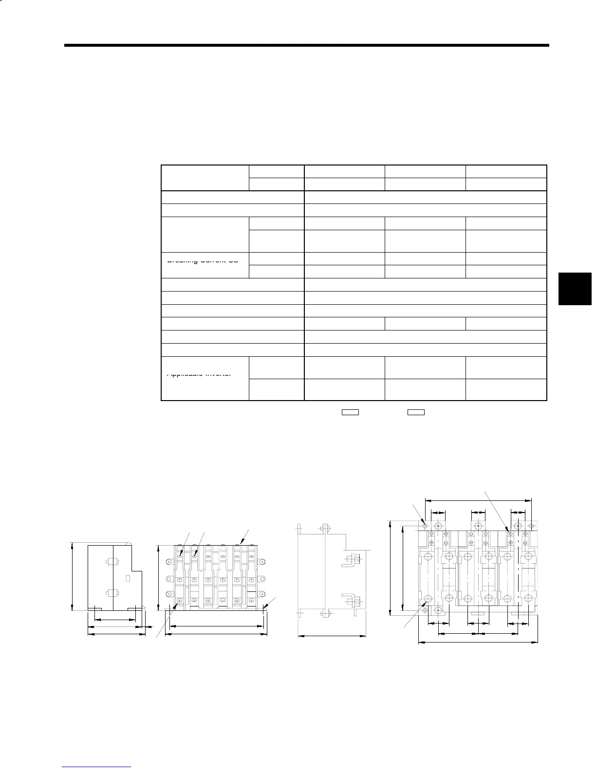
Dimensions
The dimensions are shown below in mm (inches).
85 (3.35)
97 (3.82)
65 (2.56)
Main Circuit Terminals (M5)
1
2
3
4
5
6
7
8
9
10
11
12
13
14
15
16
17
18
4-M6
Mounting
Holes
Control Circuit
Terminals (M4)
145 (5.71)
160 (6.3)
107 (4.21)
115 (4.53)
1
7
2
8
3
9
4
10
5
11
6
12
22 (0.87)
170 (6.69)
164 (6.46)
148 (5.83)
34 (1.34)
192 (7.56)
34 (1.34)
64 (2.52)
34 (1.34)
64 (2.52)
107 (4.21)
(a) Model HV-75jP4
(b) Models HV-150jP4, HV-200jP4
4-M6
Mounting
Holes
Control Circuit Terminals (M4)
Main Circuit
Terminals (M8)
22 (0.87) 22 (0.87)
Fig 14.16 Dimensions
14
 Loading...


