Appendix
15.1.1 Principle of an Inverter Drive
15 -2
15.1 Inverter Drive Basics
This section explains the basics of an inverter drive.
15.1.1 Principle of an Inverter Drive
An inverter is a frequency conversion device that converts a commercial frequency power supply to a vari-
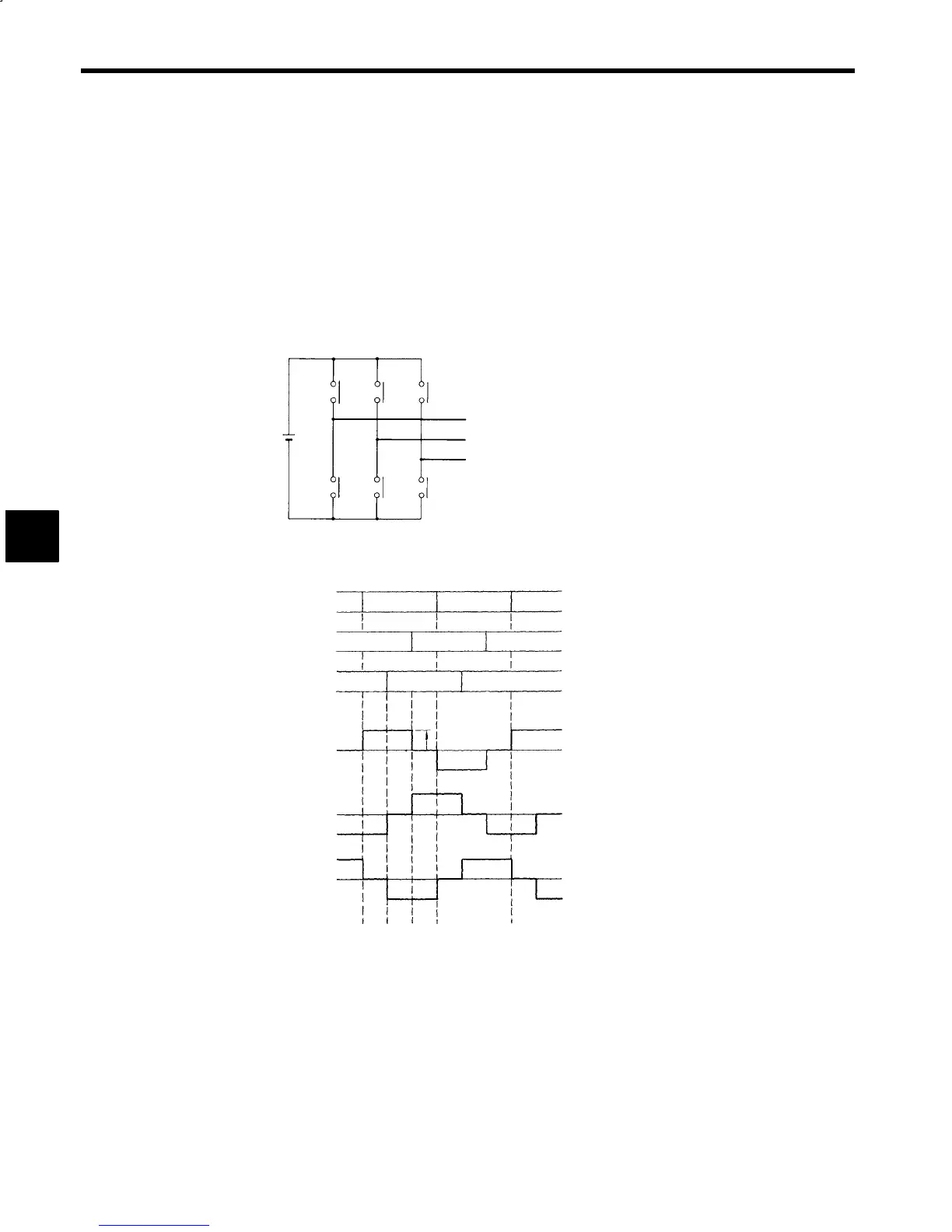
able frequency power supply. Fig. 15.1 show an operation diagram for a 3-phase voltage Inverter consist-
ing of switches, such as relay contacts. S
1
and S
4
,S
3
and S
6
, and S
5
and S
2
work as pairs to repeatedly turn
ON and OFF each half-cycle. Their ON/OFF timing is staggered by one-third of a cycle, so a square wave
AC voltage can be obtained as the output, as shown in Fig. 15.2. The frequency of the AC output voltage
is proportional to the speed at which the switches are turned ON and OFF; in other words, inversely propor-
tional to the cycle. This is the basic operating principle of an inverter.
S
1
Ed
S
3
S
5
S
4
S
6
S
2
U
V
W
Fig 15.1 Inverter Operating Principle
S
1
,S
4
Ed
S
3
,S
6
S
2
,S
5
Switches
S
1
ON
ON
ON
ON
ON
ON
ON
ON
ON
S
4
S
1
S
6
S
6
S
3
S
5
S
5
S
2
Vu-v0
Output
voltage
Vv-w0
Vw−u0
0
60°
120°
180°
360°
Fig 15.2 Switch Operation and Output Voltage
In reality, a motor drive inverter requires a variable voltage and variable frequency
(VVVF), so sine wave
pulse width modulation (PWM) control is used, as shown in Fig. 15.3. When the carrier frequency is in-
creased, sine wave current flows through the motor.
15
 Loading...


