Control Signals
4.1.1 Connecting Sequence Input Signals
4-2
4.1 Sequence Input Signals
This section provides information on the connections, functions, displays, and meaning of the sequence input
signals.
4.1.1 Connecting Sequence Input Signals
The connections of sequence input signals vary between stand-alone drives and NC systems as described
below.
J
M5A for Stand-alone Drives
Connect sequence input signals to the 6CN connector of the I/O card.
The sequence input signals can be input to the 6CN connector as 0 V, 24 V, or external common input sig-
nals. Refer to 3.4.4 Sequence Input Signal Circuits for details.
J
M5N for NC Systems
The Inverter performs serial transmission of sequence input signals with NC machines over YENET1200
communications. Refer to the manual for the NC machine for sequence input signals and input addresses.
4.1.2 Selecting Sequence Input Signals
Some functions of sequence input signals are selected by settings constants. Set the constants as shown
in the following table for the desired functions.
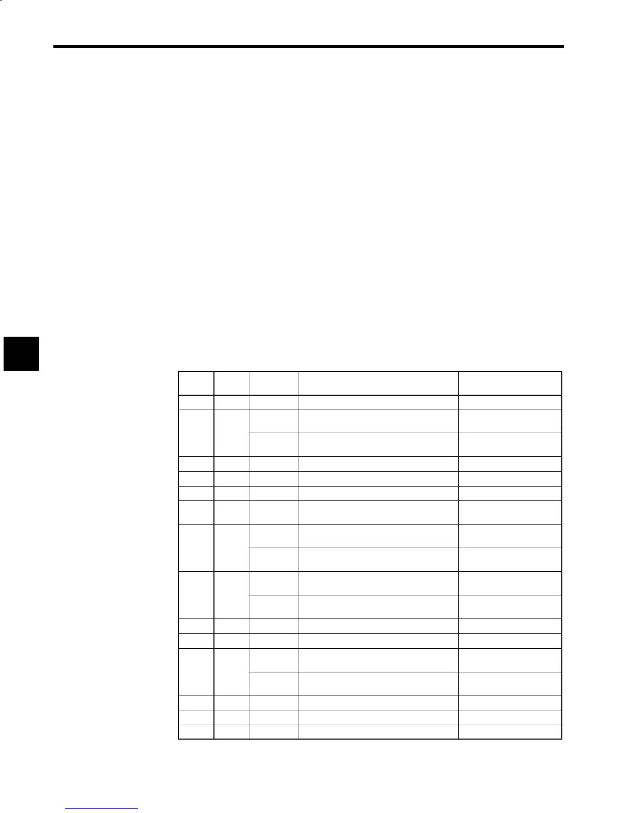
Table 4.1 Sequence Input Signals
No. 6CN
Pin No.
Signal Function Related Constants
1 5
DAS
*
Speed reference digital/analog selection
−
2 6
RDY Operation ready RDY selected at C1-37 bit 2
=0.
EMG2 Emergency stop 2 EMG2 selected at C1-37 bit
2=1.
3 7
EMG Emergency stop
−
4 8
FWD Forward run
−
5 9
REV Reverse run
−
6 10
TLH Torque limit H TLH selected at C1-36 bit 2
=0.
7 11
TLL Torque limit L TLL selected at C1-36 bit 1,
0 = 00.
INC Incremental INC selected at C1-36 bit 1,
0 = 10.
8 12
SSC Soft start cancel SSC selected at C1-36 bit 3
=0.
SV Servo mode SV selected at C1-36 bit 3 =
1.
9 13
RST
*
Error reset
−
10 14
CHW Winding selection
−
11 15
PPI P control/PI control selection PPI selected at C1-36 bit 4 =
0.
LM10
*
Load factor meter 10x selection signal LM10 selected at C1-36 bit
4=1
12 16
ORT Orientation
−
13 17
LGR L gear selection
−
14 18
MGR M gear selection
−
* The M5N for NC systems does not use the RST signal.
4