9.6 Control Signal Connector Terminal Arrangement
9-9
9.6 Control Signal Connector Terminal Arrangement
The terminal arrangement of the control signal connectors is shown below.
J
10CN Orientation Card
14 SIG− 7 ---
13 SIG+ 6 ---
12 +15 V 5 0V
11 --- 4 ---
10 +12 V 3 0V
9 --- 2 ---
8 --- 1 SS
PCB connector: 10214-52A2JL
Cable connector: 10114-3000VE
10314-52A0-008 (case)
Notes:1. The terminal arrangement is viewed from the PCB connector.
2. Connectors are manufactured by Sumitomo 3M Corporation.
J
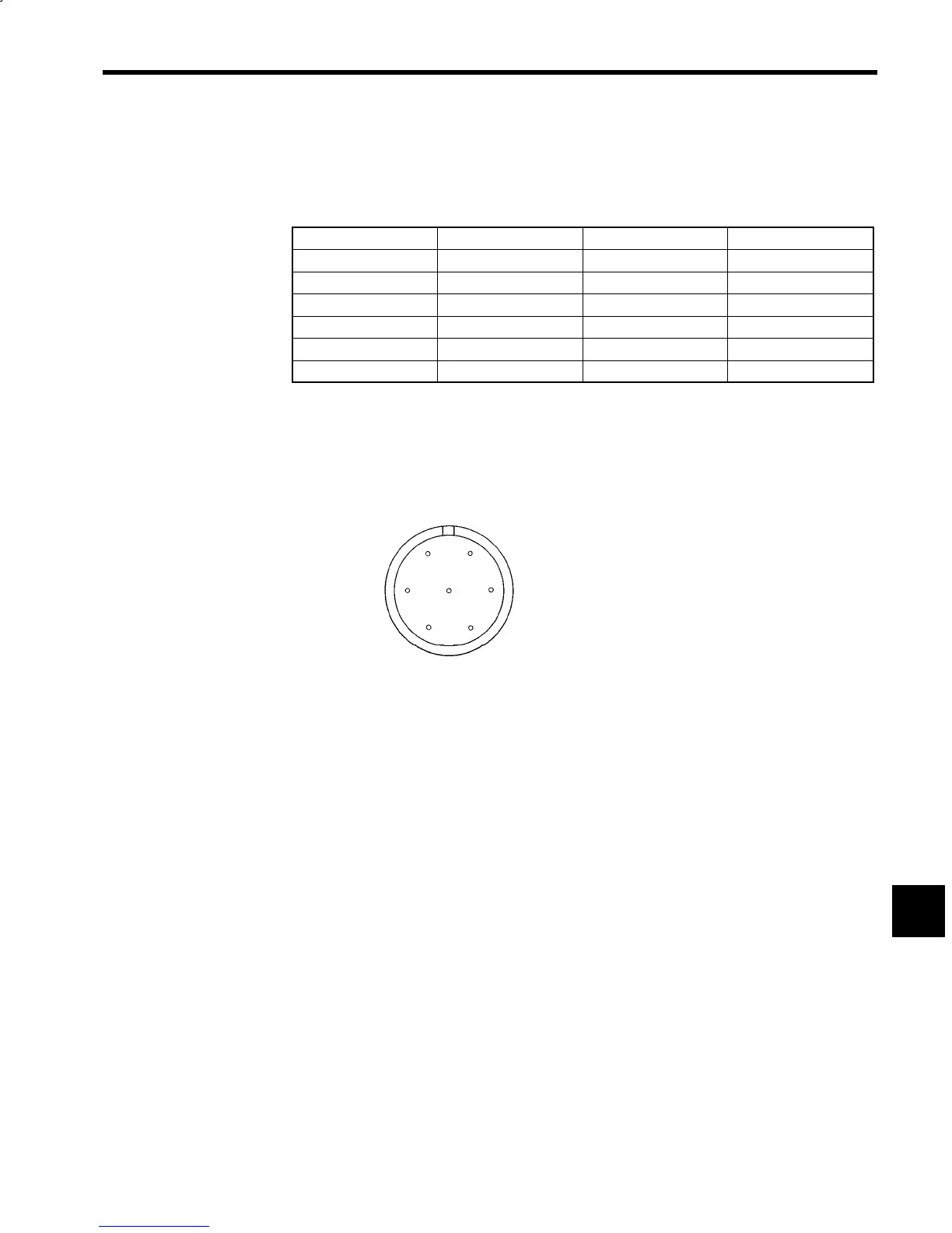
FS-1378C Magnetic Sensor
F
A
B
G
E
D
C
TRC116-21A10-7M Magnetic Sensor Connectors
TRC116-12A10-7F Cable Connectors
Notes:1. The pin arrangement is viewed from the sensor connector.
2. The cable connectors are included in the Magnetic Sensor.
3. Connectors are manufactured by Tajimi Musen Denki (KK).
Fig 9.11 Connector Terminal Arrangement
9
 Loading...


