Control Signals
4 -18
4.5 Analog Monitor Signals
The following conditions and specifications apply to analog output signals (for stand-alone drive systems M5A
only).
J
SM (Speed Meter Signal)
Connector number: 6CN
Pin number: 47
D
The motor speed can be monitored with an external speed meter connected.
D
The SM signal is a DC voltage signal that is output in proportion to the speed regardless of the direction
of rotation.
D
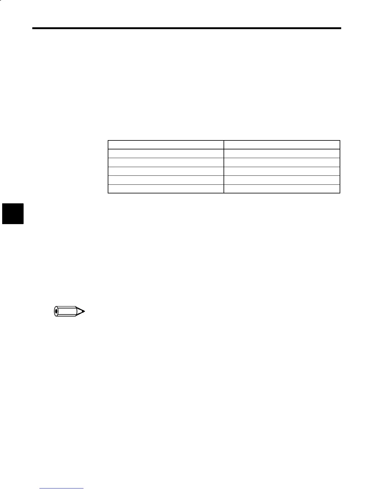
Use a voltmeter as the speed meter with the following specifications.
Item Specification
Item
Voltmeter
Operation principle
Moving coil
Rating
10 V full scale
Internal resistance
10 kΩ
Grade
2.5 or over
D
The rated SM signal output (10 V) will turn ON when the motor is rotating at the speed set in C1-26
(S
100
), the rated speed set constant.
D
The SM signal level can be adjusted with C1-16 (SM
ADJ
), the control constant.
D
The C1-16 (SM
ADJ
) control constant is for speed adjustment. The actual motor speed will not be af-
fected by changing the set value of C1-16.
D
The SM signal precision is less than 3% of the rated value when the motor is in reverse operation.
J
LM (Load Rate Signal)
Connector number: 6CN
Pin number: 50
D
The load rate signal indicates the load rate based on the rated output.
D
The meter used must have the same specifications as the one for the speed meter.
D
The load rate signal level can be adjusted with C1-17 (LM
ADJ
) for control and C1-18 (L
MFS
) for full-
scale setting.
Use 6CN pin 48 and 6CN pin 49 for the 0 V on the meter.
4
INFO