14.2 Standard Motor Specifications
14 -17
14.2 Standard Motor Specifications
This section explains the standard motor specifications.
14.2.1 Outline
The AC main axis motor is a squirrel cage induction motor ideal for the main axis drive of machine-tools
and high-speed drives on industrial devices. There are two series of models: Flange models for easy mount-
ing to machinery, and foot-mounted models. The features of both are given below.
J Wide Rated Output Ranges
The application of high-precision bearings, a high rigidity frame design, and other design elements enables
using the motor within the following ranges: Maximum speed of 8,000 min
−1
(rated output range of 1:5.3)
at 7.5 kW maximum, maximum speed of 6,000 min
−1
(rated output range of 1:4) from 11 kW to 22 kW,
and maximum speed of 4,500 min
−1
(rated output range of 1:3.9) at 30 kW minimum. The winding selec-
tion motors have even wider rated output ranges, and achieve a rated output range of 1:12 without using
a speed change gear. Compact magnetic contactors having a transfer contact structure specialized for
winding selection are provided. For detailed specifications of the magnetic contactor, refer to 14.3.3 Mag-
netic Contactor Specifications for Winding Selection.
J
Low Vibration
Low vibration is achieved by miniaturizing the motor and adjusting the dynamic balance for high-speed
drive.
J
High Reliability
The motor protection conforms to IP44, and the speed detector uses a highly reliable 1024 P/R magnetic
field encoder.
J
Cooling System
In all motors, cooling air enters from the load machine side and exits from the opposite side, avoiding expo-
sure of the machine to the exhaust. If the opposite air direction is preferred because of the machine configu-
ration, the cooling structure can be changed accordingly.
J
400 V Series
The mounting dimensions and other dimensions are the same as for the Standard 200 V Series. The Motor
Cooling Fan, however, is special for the 400 V Series.
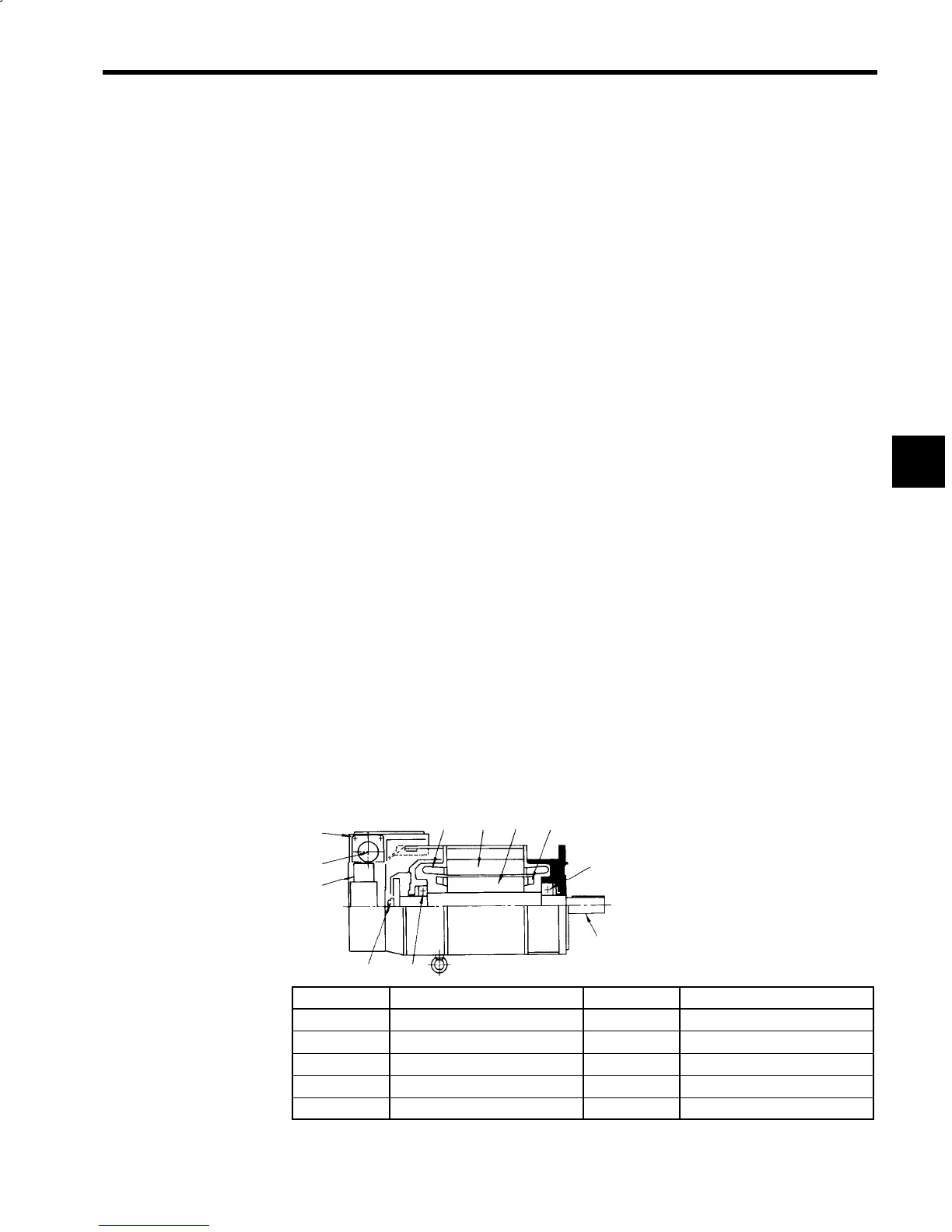
14.2.2 Configuration
The motor configuration is shown in the following diagram.
1
2
3
45
6
7
8
9
10
2
Number
Name Number Name
1 Output shaft 6 Stator winding
2 Bearings 7 Terminal box
3 Rotor 8 Cable socket
4 Rotor short environment 9 Cooling fan
5 Stator 10 Encoder
Fig 14.6 Motor Configuration
14
 Loading...


