8.3 Orientation Specifications
8-5
8.3 Orientation Specifications
This section explains the specifications for devices required for encoder orientation.
8.3.1 Standard Specifications
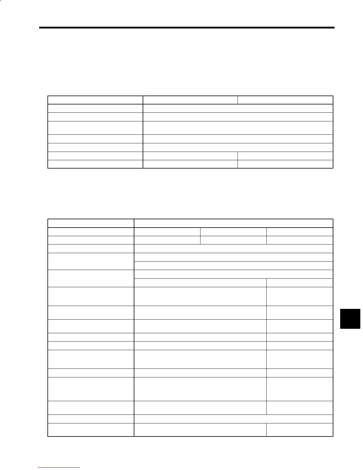
The following table shows the standard specifications for encoder orientation.
Table 8.1 Standard Specifications
Item Load Shaft Encoder Motor Encoder
Positioning Method
Absolute or incremental
Positioning Detection Method
Main shaft angle detection using a load shaft or motor encoder phase-A, -B, and -C pulses
Stop Position (See *1.)
Positioning to the position set internally or via external reference, using the load shaft origin (see
*2) as standard. Angle resolution is 0.088
_
(= 360
_
/4096)
Stop Position Repeat Accuracy (See *1.)
±0.2
_
Max.
Resistance Torque (See *1.)
Continuous rated torque/±0.1
_
displacement (See *3.)
Orientation Card
Code number: ETC62613X Not used
Encoder Model
NE-1024-2MDF-068 (Load shaft mounted) UTMSI-10AAG (Built-in motor encoder)
* 1. Excludes functional deviation, such as backlash and eccentricity.
* 2. The origin is obtained using the number of offset pulses set in constant memory from the rising edge of the Encoder phase-C
pulse during forward rotation.
* 3. The continuous rated torque may not be output depending on the gain setting. Also, displacement may be larger for rapid load
variations.
8.3.2 Load Shaft Encoder Specifications
The load shaft encoder specifications are shown in the following table.
Table 8.2 Load Shaft Encoder Specifications
Item Details
Model
NE-1024-2MDF-068-11 NE-1024-2MDF-068-12 UTMSI-10AAG
Maximum Speed (min
−1
) (See note.)
6,000 8,000 10,000
Power Supply
5 VDC ±5%, 350 mA
Number of Pulses
Phases A and B: 1,024 pulses/rotation
Phase C: 1 pulse/rotation
Output
Symmetrical output using a line driver for all phases in common
AM26LS31 SN75158
Maximum Response Frequency
200 kHz Phases A and B: 188 kHz
Phase C: 183 kHz
(11,000 min
−1
)
Accumulative Pitch Error
Within 20% of phase-A and phase-B signal cycle Within 50% of phase-A and
phase-B signal cycle
Pitch Error
Within 10% of phase-A and phase-B signal cycle Within 12.5% of phase-A and
phase-B signal cycle
Input Shaft Inertia
170x10
−3
kgf
S
cm
S
s
2
max. 58.7 x 10
−3
kgf
S
cm
S
s
2
Input Shaft Torque
1 kgf
S
cm max. ---
Input Shaft Tolerance Load
Thrust: 5 kg (11 lb) max (stopped), 10 kg (22 lb) max. (operating)
Radial: 10 kg (22 lb) max (stopped), 20 kg (44.1 lb) max. (operat-
ing)
---
Construction
IP = 54 (connectors facing downwards) Main shaft mounted
Output Connectors
Main Unit: 97F3102E20-29P
Cable: MS3106A20-295
Manufactured by DDK
Main Unit: MLR-12 model
Cable: MLP-12 model
Manufactured by Nihon Crimp
(KK)
Weight
1 kg (2.2lb) 0.33 kg (0.728 lb) (Encoder
disk)
Operating Temperature Range
0to60°C (32 to 140°F)
Humidity
85% max. (with no condensation) 10% to 95% (with no condensa-
tion)
8
 Loading...


