Wide Constant Power Control Using Winding Selection
7.5.1 M Code Winding Selection Method
7-6
7.5 Winding Selection Methods
When performing winding selection, design the reference circuits referring to the following three methods, to
make sufficient use of the motor characteristics.
7.5.1 M Code Winding Selection Method
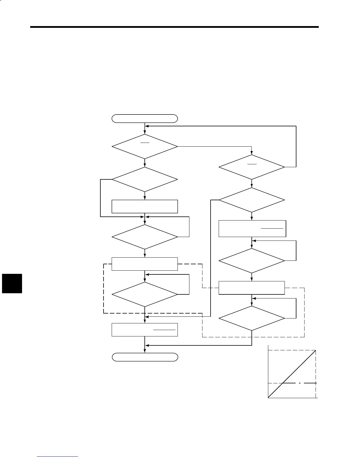
For the main shaft drive of the machine-tool, view the winding selection as an electric gear, and use the
numeric control M codes (M41: Low-speed winding, M42: High-speed winding) as shown in the flow-
chart and timing chart below.
Start
M42
Low speed to
high speed
M41
High speed to
low speed
S reference ≥ KXS
CHW
S reference
End
S reference < K X S
CHW
Does speed agree (AGR)?
Switching completed
(CHWE)?
NO
YES
YES
YES
YES
NO
YES
YES
NO
NO
NO
YES
YES
NO
NO
K
NO
Speed reference =
Speed reference = S
CHW
Speed reference =
S reference
K
Winding selection
(CHW turns OFF.)
Winding selection
(CHW turns ON.)
Switching completed
(CHWE)?
Does speed agree (AGR)?
* 1. Operations within the dotted lines are Inverter internal signal processes.
*2.M41: Low-speed winding selection
M42: High-speed winding selection
S reference: Main shaft rotation speed reference (main shaft)
S
CHW
: Winding selection speed (Motor)
(In the diagram, S
BH
≥ S
CHW
≤ S
ML
)
K: Gearbox ratio (When main shaft is traveling at 4,000 min
−1
,
if the Motor is operating at 5,000 min
−1
, K = 0.8.)
Speed reference: Motor speed reference.
The relationship between the speed reference and S reference for M41
and M42 is shown in the diagram on the right.
Fig 7.4 Flowchart
7
1.0
S
CHW
0
1.0
M42
M41
Speed reference
S reference