3.4 Wiring Control Circuit Signals
3-29
J
Control Signal Functions
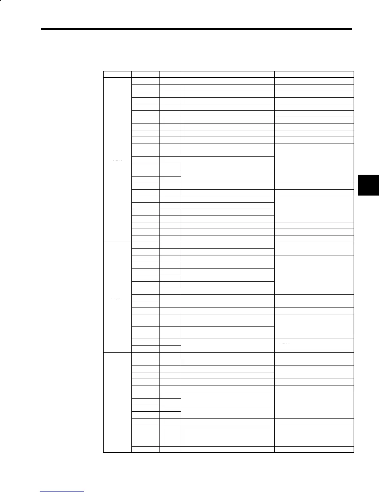
Table 3.12 Control Circuit Signals (1CN to 4CN)
Connector Signal No. Function Signal Level
+24VIN 1 − −
/EXT1 2 − −
/EXT2 3 − −
ESP0 4 − −
ESP1 5 − −
ALM+ 6 − −
ALM−
7 − −
ALMC 8 − −
BAT− 9 − −
BAT+ 10 − −
PAO 13
*PAO 14
Encoder phase A signal output
1CN
PBO 15
R
-
spec
cat
on
*PBO 16
Encoder phase B signal output
Line driver
PCO 11
+5 V
*PCO 12
Encoder phase C signal output
SS 17 Shield (0V) −
0V 18 0V −
D1 to D12 19 to 30 12-bit digital references 1 through 12
EXTCOM 31 12-bit digital signal common
24 VDC
24VCOM 32 12-bit digital signal power supply +24 V
Closed current: 5 mA
0VCOM 33 12-bit digital signal power supply 0 V
VCC 34 − −
MNTR1 35 − −
MNTR2 36 − −
+5V 4, 5, 6 +5V power supply for encoder
+5V
0V 1, 2, 3 Encoder power supply common
Load current: 350 mA or less
PA 16
*PA 17
Encoder phase A signal input
PB 18
R
-
spec
cat
on
*PB 19
Encoder phase B signal input
Line receiver
PC 14
+5 V
*PC 15
Encoder phase C signal input
2CN
THSA 8
THSB 9
Motor thermistor signal −
SS 7 Shielded wire connection (0V) −
+24V 10
+24V power supply for winding selection
device
CC 11
Winding selection device power supply
common
+24V
CA1 12
+24V
CA2 13
Winding selection status signal
Load current: 10mA or less
+5 V 7, 9, 14 +5 V power supply
0V 1, 3, 5 0V
+5 V
3CN
TX 2 Send data (Inverter to Operator)
(option)
RX 4 Receive data (Operator to Inverter)
−
OP1 6 Not used. −
OP2 8 Not used. −
S 2
I/O si
nal for YENET1200 communica-
*S 1
-
tion
R
-
spec
cat
on
S 7
I/O si
nal for YENET1200 communica-
Line driver/receiver
*S 6
-
tion
+5 V
4CN
FG 5 Frame ground −
I/O si
nal for YENET1200 communica-
RS-422A specification
R 4
-
tion (with terminating resistance)
Line driver/receiver
+5 V
SH 3, 8 Shielded wire −
Note: The 4CN connector is for M5N models for NC systems.
3
 Loading...


