Wiring
3.4.3 Control Signal Functions
3-30
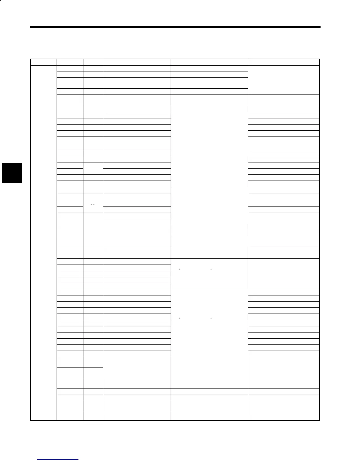
Table 3.13 Control Circuit Signals (6CN)
Connector Signal No. Function Signal Level Related Constants
+15V 1 +15V output +15V Load current: 10mA or less
SS 2 Shield (0V) −
-
-
SCOM 3 Analog speed reference input
0to±10V
(Input impedance: 50kΩ)
-
,
,
-
C1-11, 12
0V 4 Analog speed reference 0V −
DAS 5
Digital/analog speed reference
selection
C1-36 bit 7
RDY
Operation ready Selected when C1-37 bit 2=0
EMG2
6
Emergency stop 2 Selected when C1-37 bit 2=1
EMG 7 Emergency stop −
FWD 8 Forward run −
REV 9 Reverse run −
TLH 10 Torque limit H
Selected when C1-36 bit 2=0
C1-26, C1-38 bit 2
TLL
Torque limit L Selected when C1-36 bit 1, 0=00
INC
11
Incremental Selected when C1-36 bit 1, 0=10
SSC
Soft start cancel Selected when C1-36 bit 3=0
SV
12
Servo mode
Selected when C1-36 bit 3=1
RST 13 Fault reset
−
CHW 14 Winding selection
urrent w
en c
ose
:
m
−
PPI 15 P control/PI control selection Selected when C1-36 bit 4=0
ORT
16
Orientation
Selected when C1-40 bit 3=0
C1-39 bit 0
NCORT
NC orientation Selected when C1-40 bit 3=1
LGR 17 L gear selection
MGR 18 M gear selection
C1-27, 28, 29
EXT-
COM0
19 to 21
Sequence input signal power sup-
ply common
−
6CN
24VCOM 22, 23
Sequence input signal power sup-
ply 24V
−
0VCOM 24, 25
Sequence input signal power sup-
ply 0V
−
FC0 26 Fault code 0
FC1 27 Fault code 1
Open-collector output
FC2 28 Fault code 2
Exclusive-use for 24VDC
−
FC3 29 Fault code 3
Load current: 50mA or less
COM2 30 Fault code signal common
ZSPD 33 Zero-speed C1-19
AGR 34 Speed agree C1-20, C1-38 bit 6
SDET 35 Speed detection C1-21, C1-22, C1-40 bit 2
TDET 36 Torque detection C1-23
TLE 37 Torque limit
Open-collector output
−
ORG 38 Load origin
Exclusive-use for 24VDC
−
ORE 39 Orientation completion
Load current: 50mA or less
C2-09, 10 or C3-09, 10
CHWE 40 Winding selection completion
−
FLTL 41 Fault (OFF at fault) −
TALM 46 Minor fault −
COM1 42 Sequence output signal common −
FLTNO 43
Relay contact output
FLTNC 44
Closed between 43 and 45 at fault
xc
us
ve-use
or
Load current: 1A or less
−
FLTCOM 45
Open between 44 and 45 at fault
Minimum permissible load: 10 mA
(as reference value)
SM 47 Speedometer output 0 to +10V Load current: 2mA or less C1-16, 54
0V 48 0V for speedometer − −
LM 50 Load ratio meter output 0 to +10V Load current: 2mA or less
C1-17, 54, 18, C1-40 bit 4
0V 49 0V for load ratio meter −
C1-38 bit 1, 0
C1-38 bit 7
Note: The 5CN connector is for M5A models for stand-alone drive.
3
 Loading...


