9.3 Orientation Specifications
9-5
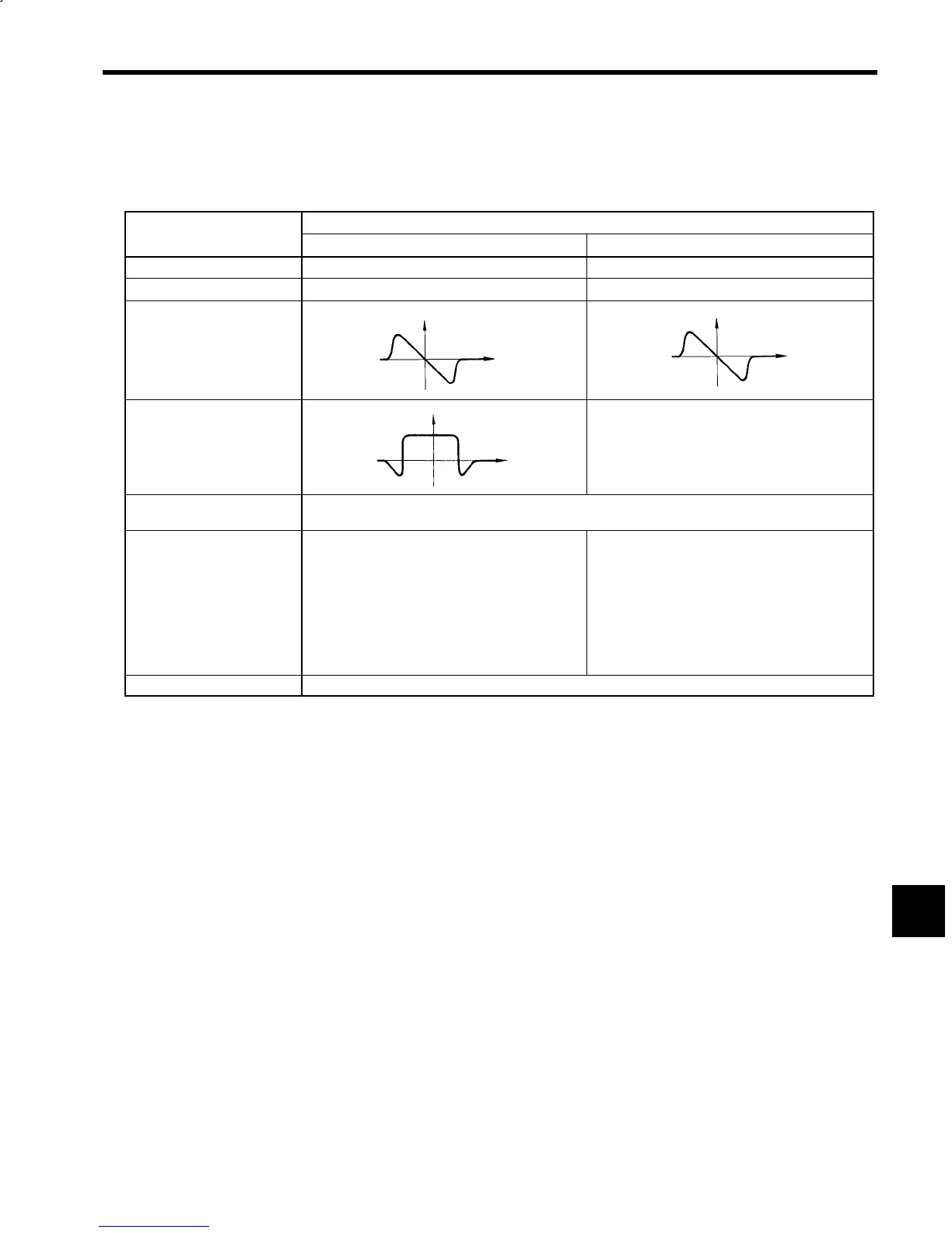
9.3.3 Magnetic Sensor Specifications
The specifications for the Magnetic Sensor are shown in the following table.
Table 9.3 Magnetic Sensor Specifications
Item
Details
FS-1378C FS-200A
Power Supply Voltage
15 VDC ±5% 12 VDC ±10%
Consumption Current
100 mA max. 50 mA max.
Position Signal for Control
Level
Offset
Output Impedance
±4 V min.
±0.2 V max.
1.5 kΩ
0
Output
Displacement
±8 V min.
±0.2 V max.
1.5 kΩ
0
Output
Displacement
Position Signal for Monitor
Range
Offset
30_ min.
*1
(+24 V max.)
±0.5 V max.
0
Output
Displacement
---
Ambient Operating Tempera-
ture
−10 to 50_C
Output Terminals
Supplied with round connectors
Manufacturer: Tajimi Musen Denki (KK)
A: Position signal +
B: SG
C: 15 V
D: Position signal −
E: Range signal −
*2
F: Range signal +
*2
Supplied with 5-m 6-mm-diameter, 4-core cabtire
cable
Wiring:
Red: 12 V
Black: SG
Green: + output
White: − output
Manufacturer
(KK) Makome Research Center
* 1. When Magnet is mounted on 120-mm-diameter load shaft rotating part.
* 2. The range signals on terminals E and F can be used for monitoring.
9
 Loading...


