Orientation Control Using an Encoder
8 -14
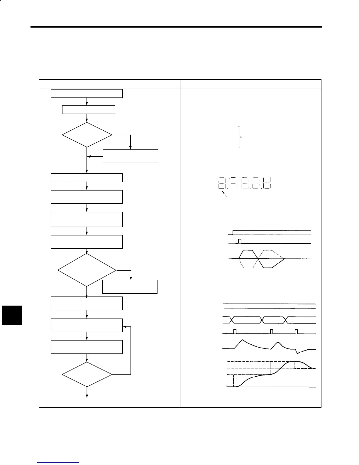
8.9 Encoder Orientation Control Mode Adjustment Procedure
Adjust the encoder orientation according to the following flowchart. Be sure to perform the following adjust-
ments if the Motor, Inverter, or Encoder are replaced.
Adjustment Item and Procedure Details
Does shaft
stop at correct posi-
tion?
NO
YES
NO
YES
NO
YES
Turn ON the power supply.
Make the initial settings.
Is gear ratio set-
ting correct?
Adjust controller gear
ratio constant.
Do not hold the key
down.
Select H gear.
Turn ON orientation signal (ORT).
Tuneup incomplete error (AL-60)
is displayed.
Press the STOP and RESET
Keys and release them together.
Rotate
motor forwards and
reverse. Does load
shaft stop at ori-
gin?
Perform error diagnosis
and correct error.
Select control constant display
for load shaft origin (C2-01).
Set the origin data, and press
the ENTER Key.
Shaft stops at new origin.
(1)
Initial Settings: Change Constants Using Digital Operator
S Turn OFF the orientation selection (bit 0) of selection signal 4 (C1-39).
S Turn OFF the tuneup operation selection (bit 4) of orientation selection
signal 1 (C2-22).
Gear Ratio Constants
S C1-27: Gearbox ratio (H)
S C1-28: Gearbox ratio (M)
S C1-29: Gearbox ratio (L)
0.0400 to 2.500
Tuneup Operation
Orientation signal (ORT) is lit
Input Signal Check
Interface input status (U1-09)
Note: During tuneup, the orientation completion signal (ORE) is not
output.
Orientation signal
STOP Key and
RESET Key
Load shaft speed
FWD
REV
Load Shaft Origin
0
P
1
P
3
P
2
0
P
1
P
2
P
3
Orientation signal
0
0
FWD
REV
Load
shaft
position
(When 0 < P
1
<P
3
<P
2
)
Origin data
ENTER Key
Load shaft speed
8
 Loading...


