2.4 Attaching the Digital Operator
2-9
2.4 Attaching the Digital Operator
WARNING
D Disconnect all power before removing Digital Operator (JVOP-132). Then wait for the time de-
scribed on warning labels after main circuit power supply and control power supply are discon-
nected, and all LEDs of the Inverter and the Converter are extinguished.
Failure to observe this warning can result in an electric shock.
CAUTION
D Do not use any screws other than the ones provided to mount the cable holder.
Otherwise, the cable holder will not be attached securely.
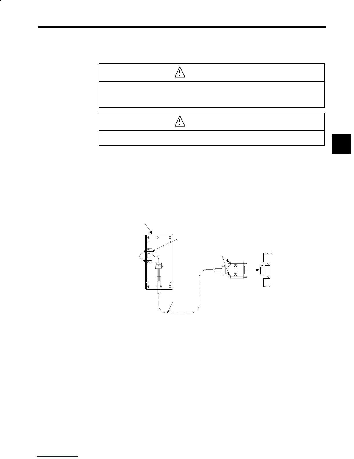
The VS-626M5 can support the Multi-functional Display Digital Operator (JVOP-132) as an option. The
Exclusive-use Extension Cable (72616-W5301 or 72616-W5303) is required when connecting the Digital
Operator with the Inverter. Use 3CN to attach the digital operator firmly as follows.
D
Turn OFF the Inverter power supply.
D Connect the extension cable on both Inverter and Digital Operator. (See Fig. 2.12.)
D
After inserting the connector into the Inverter, tighten two connector screws to prevent the connector
from being removed.
D
Install the cable holder on the Digital Operator with the provided tapping screws to prevent the cable
from dropping.
Digital Operator
(Back of JVOP-132)
Cable holder
(Make sure it’s not reversed.)
Attach the cable
holder with tapping
screws M3×10.
Connector code for
digital operator con-
nection
3CN
Connector screws
Control PC board
Extension cable
Fig 2.12 Extension Cable Installation
2
 Loading...


