Appendix
15.4.4 Analog Monitor Signals (M5A Stand-alone Drive)
15 -22
15.4.4 Analog Monitor Signals (M5A Stand-alone Drive)
The monitor signals output from the Inverter are speedometer signals and load rate meter signals. Use a
10 V full-scale voltmeter or a PLC Analog Input Module. Use the monitor signal wires at 20 m max. If
the length of the wires exceeds 20 m, or noise is superimposed on the signal wires, install an isolation am-
plifier midway along the line to good effect.
For signal details, refer to 4.5 Analog Monitor Signals (for Stand-alone Drives).
15.4.5 YENET1200 Signals (M5N NC Drive)
The YENET1200 communications system for Yaskawa NC Units sends and receives data such as speed
references, sequence I/O signals, motor speed, and failure information using serial communications. These
serial communications signals are connected to 4CN on the YENET1200 Card. If an Inverter is installed
at the terminal, connections must be made to 4CN and 1CN for terminal processing.
For details of YENET1200 communications, refer to the Yaskawa NC Unit operation manuals.
Inverter
4CN−2
4CN−6
4CN−4
4CN−3
1CN−7 ALM−
1CN−8 ALMC
S
S
R
SH
*
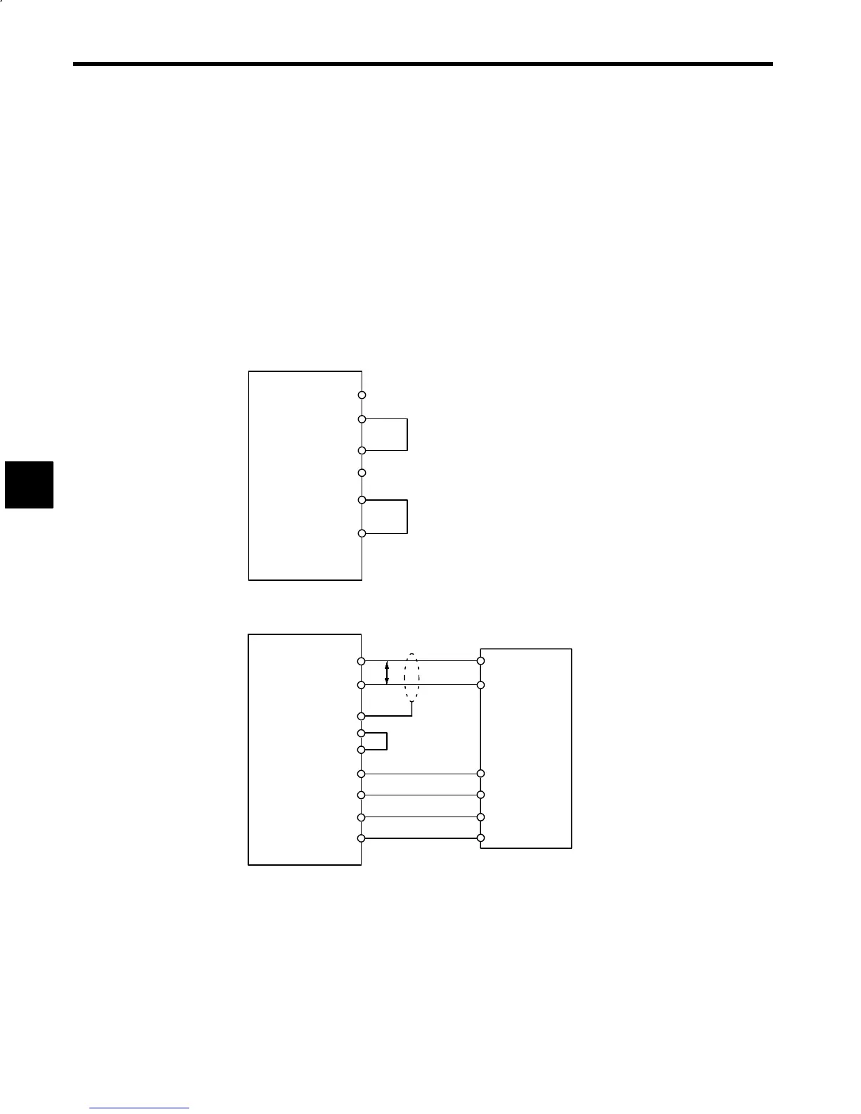
Fig 15.25 Connection when the Inverter is the Terminal Unit
Inverter
4CN−1
4CN−2
4CN−3
4CN−8
1CN−1 +24 VIN
1CN−4 ESP0
S
S
SH
SH
NC Unit
1CN−8 ALMC
1CN−6 ALM+
4CN−5
FG
P
*
Fig 15.26 Connection between NC Unit and Inverter
15
 Loading...


