15.4 Interface Design
15 -19
15.4 Interface Design
This section explains the interface design for the signals.
15.4.1 Sequence Input Signals
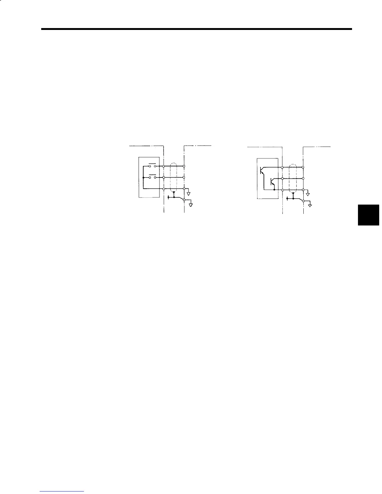
Among the input signals, 12-bit digital references (1CN) and sequence input signals (6CN), which control
the operation status of forward rotations, reverse rotations, and torque limits, etc., can be used in common
with the relay contacts and transistor switches, as shown in Fig. 15.20. Also, the signal circuit common
can be selected from the 0 V common, which uses the Inverter power supply, the 24-V common, or the
external common, which uses a separate 24-V power supply (20 to 26 V). The wiring differs depending
on the input method, so refer to Fig. 15.21 to perform the wiring correctly. Also, the 1CN common and
6CN common are isolated, so each common can be selected independently. For signal details, refer to 4.1.4
Details on Sequence Input Signals.
PLC Inverter
Relay Output
Module
(a) Relay Contact
Forward
rotation
Reverse
rotation
0V
SS
Relay contact capacity
35 VDC min.
Rated current 100 mA min.
PLC
Inverter
Transistor Output
Module
Forward
rotation
Reverse
rotation
0V
SS
Voltage resistance 35 VDC min.
Rated current 100 mA min.
(b) Transistor (Open Collector)
Fig 15.20 Operation Signals Connection Examples
15
 Loading...


