Appendix
15.2.1 Torque
15 -6
15.2 Basic Inverter Drive mechanics
This section explains the torque, motive power, and inertial moment that are the basis of selecting motor and
inverter capacities.
15.2.1 Torque
Torque is a moment of force that causes the rotation axis on the rotator to rotate about a center. As shown
in Fig. 15.7, when external force f (N) is used in a tangential direction at point P, which is separated by
the distance r (m) only from the center of rotation O, the torque T can be expressed using the following
formula.
T = f ⋅ r (N
⋅
m)
r
O
P
f
0
f
Fig 15.7 Torque Definition
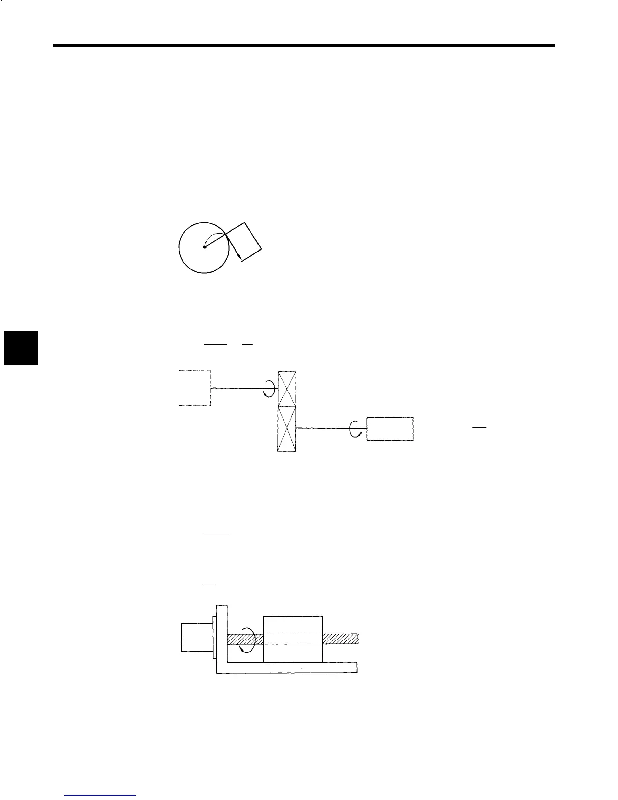
Also, as shown in Fig. 15.8, if a gearbox is used, the torque increases and decreases proportional to the
shifting gears, so taking motor axis speed N
M
(min
−1
) and load axis speed N
L
(min
−1
), the motor axis calcu-
lated torque T
M
(NSm) can be expressed using the following formula.
T
M
=
N
L
T
L
N
M
=
T
L
a
(N
⋅
m)
Motor
Motor axis
N
M
(min
−1
)
T
M
N
L
(min
−1
)
Load axis
T
L
J
L
(kg m
2
)
Load machinery
(Gear ratio a =)
N
L
N
M
Inertial moment
⋅
Fig 15.8 Torque when a Gearbox Is Used
15.2.2 Rotator and Linear Operator Outputs
Using torque T (NSm) on the rotator, the output P
R
during rotation at speed N (min
−1
) can be expressed
using the following formula.
P
R
=
2πNT
60
= 0.1048NT
(W)
As shown in Fig. 15.9, taking the force F (N), which is used on the speed V (m/min.) and the load, the output
P
L
when performing linear operations can be expressed using the following formula.
P
L
=
FV
60
= 0.0167FV
(W)
N (min
−1
)
V (m/min)
W (kg)
Bed
Ball screw
Fig 15.9 Linear Operation Output
15
 Loading...


