10.3 Magnetic Sensor Orientation Constants
10-11
10.3 Magnetic Sensor Orientation Constants
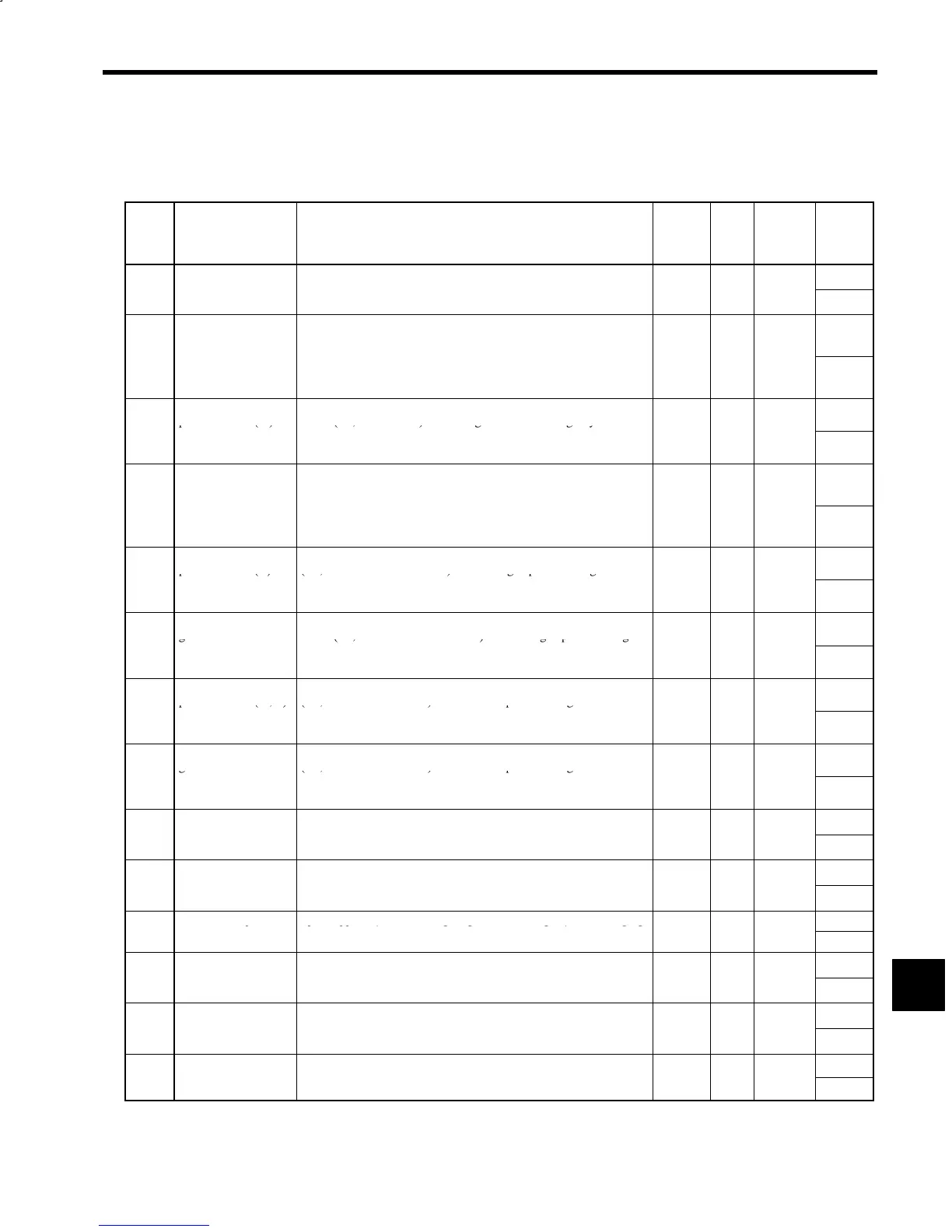
The magnetic sensor orientation constants are listed in the following table.
Table 10.3 Magnetic Sensor Orientation Constants
Con-
stant
No.
Name Explanation Change
*
1
Unit Standard
Setting
Upper
Limit/
Lower
Limit
Load Shaft Position-
Mechanical origin of the load shaft. Set difference from magnetic
2.00
C3-01
ng
r
g
n
P
ORG
sensor s
gna
n
egrees.
Yes Deg. 0.00
−2.00
Position Control Pro-
portional Gain (H)
Position control proportional gain when high-speed gear is selected
(i.e., MGR and LGR are OFF) or when high-speed winding is se-
lected
i.e.
CHW is OFF
.
99
C3-02
K
PH
.
.,
.
Increasing K
PH
increases rigidity.
Speed reference (pps) = K
PH
× Position tolerance (pulses)
Yes 1/sec 15
1
Position Control Pro-
portional Gain (M)
Position control proportional gain when medium-speed gear is se-
lected (i.e., MGR is ON). Increasing K
PM
increases rigidity.
99
C3-03
K
PM
Speed reference (pps) = K
PM
× Position tolerance
(pulses)
Yes 1/sec 15
1
Position Control Pro-
portional Gain (L)
Position control proportional gain when low-speed gear is selected
(i.e., LGR is ON) or when low-speed winding is selected (i.e., CHW
is ON
.
99
C3-04
K
PL
.
Increasing K
PL
increases rigidity.
Speed reference (pps) = K
PL
× Position tolerance (pulses)
Yes 1/sec 15
1
Speed Control Pro-
portional Gain (H)
Speed control proportional gain when high-speed gear is selected
(i.e., MGR and LGR are OFF) or when high-speed winding is se-
255
C3-05
K
VHO
lected (i.e., CHW is OFF) in orientation control (i.e., ORT is ON).
Torque reference P = K
VHO
× Speed tolerance
Yes %/Hz 40
1
Speed Control Inte-
gral Time Constant
Speed control integral time constant when high-speed gear is se-
lected (i.e., MGR and LGR are OFF) or when high-speed winding is
1000
C3-06
(H)
τ
VHO
selected (i.e., CHW is OFF) in orientation control (i.e., ORT is ON).
Torque reference I = Torque reference P × Time /τ
VHO
Yes ms 100
5
Speed Control Pro-
portional Gain (M, L)
Speed control proportional gain when low-speed gear is selected
(i.e., MGR or LGR is ON) or when low-speed winding is selected
255
C3-07
K
VLO
(i.e., CHW is ON) in orientation control (i.e., ORT is ON).
Torque reference P = K
VLO
× Speed tolerance
Yes %/Hz 40
1
Speed Control Inte-
gral Time Constant
Speed control integral time constant when low-speed gear is selected
(i.e., MGR or LGR is ON) or when low-speed winding is selected
1000
C3-08
(M, L)
τ
VLO
(i.e., CHW is ON) in orientation control (i.e., ORT is ON).
Torque reference I = Torque reference P × Time /τ
VLO
Yes ms 100
5
Positioning Comple-
Detection width for outputting completion signal when the load shaft
20.0
C3-09
on
e
ec
on
Z
FIN
approac
es
es
op re
erence pos
on.
Detection width is stop reference position ±Z
FIN.
No Deg. 0.5
0.0
Positioning Comple-
Set value for canceling completion signal when the load shaft is
20.0
C3-10
on
ance
Z
CAN
move
a
er comp
e
on s
gna
sou
pu
.
Cancel width at stop reference position ±Z
CAN.
No Deg. 1.0
Z
FIN
Orientation Speed Speed applied (after detecting magnetic sensor signal) until changing
−
600
C3-11
S
ORT
to the servo loop during orientation.
No min
−
400
40
BCD Stop Position
Completion signal cancel angle per minimum increment for deter-
-
180.0
C3-12
e
erence
eso
u
on
P
BCD
m
n
ng s
op pos
on
or
ncremen
a
pos
on
ng w
com-
mand after stopping at home position.
No Deg. 1.0
0.5
Virtual Stop Position
Stop position offset for smoothing stop operation when the servo
10.0
C3-13
se
P
IMG
oop
s use
.
When Z
FIN
is reached, offset becomes 0.
No Deg. 0.0
0
Orientation Speed
Speed changing ratio for gradually reducing orientation speed to
100
C3-14
C
ang
ng Rat
o re
uce gear no
se w
en sw
tc
ng from or
entat
on spee
to servo
loop speed.
No --- 0
0
10
 Loading...


