Control Constants
10 -12
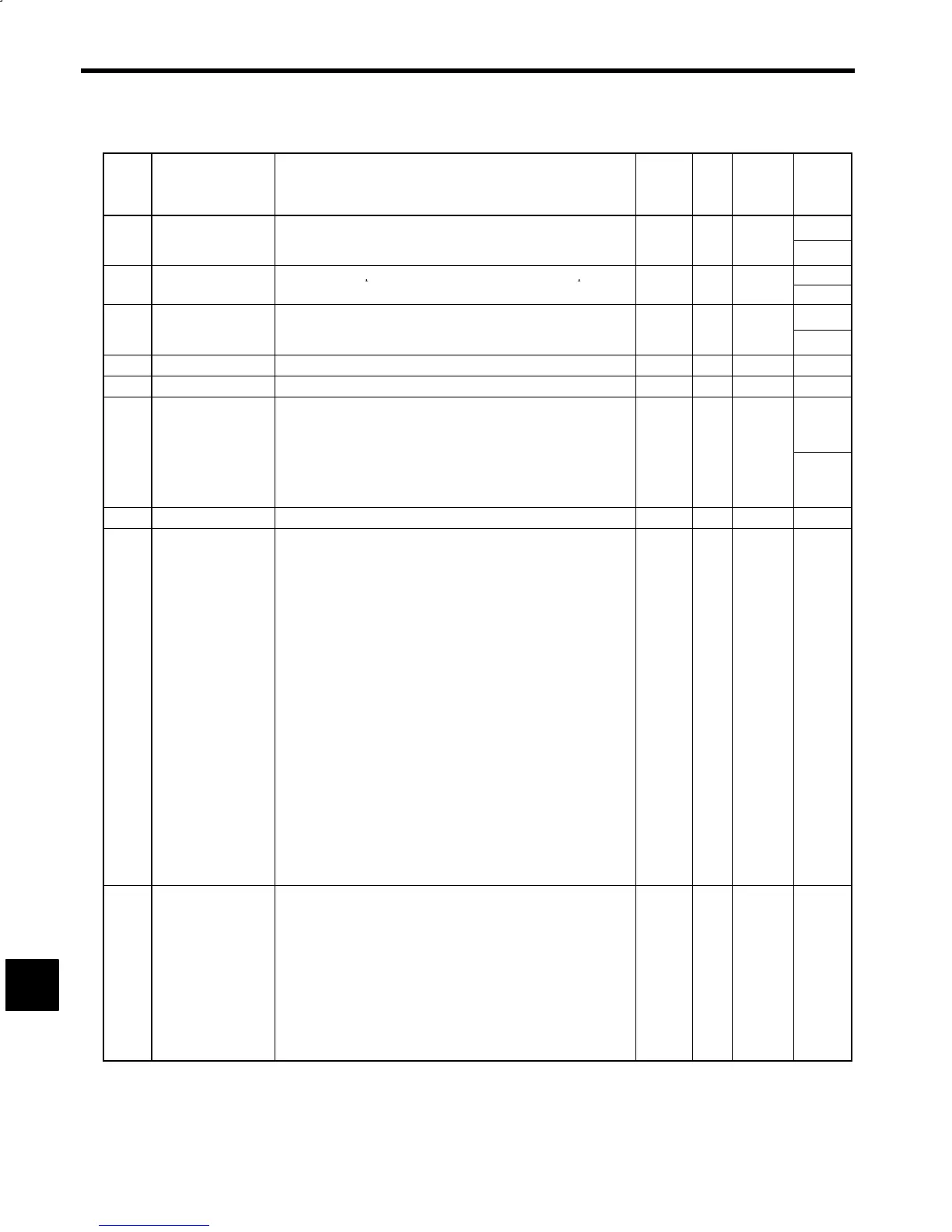
Table 10.3 Magnetic Sensor Orientation Constants (continued)
Con-
stant
No.
Name Explanation Change
*
1
Unit Standard
Setting
Upper
Limit/
Lower
Limit
Starting Soft Start
Soft start time for accelerating from stop to orientation speed. Use this
50
C3-15
me
T
SFO
parame
er
ore
uce gear no
se a
s
ar
ng.
Acceleration rate is (500 min
−1
)/sec.
No ms 0
0
Flux Level Flux level at completion of orientation. Motor noise and torque
100
C3-16
φ
ORT
change in proportion to flux level.
No --- 60
15
Orientation Speed
Reduction coefficient to set orientation speed in proportion to the
32767
C3-17
e
uc
on
oe
c
en
K
SOR
rave
ng ang
e
or
ncremen
a
pos
on
ng.
No --- 0
0
C3-18
--- ---
--- --- --- ---
C3-19
--- ---
--- --- --- ---
Sensor Signal Stan-
dardization Angle
θ
SEN
Angle for standardizing magnetic sensor signal detection sensitivity
θ
SEN
= 180°× Detection range (mm (inches)) ÷ Mounting radius ÷ π
Set 20.0 to θ
SEN when
θ
SEN
> 20.0.
20.0
C3-20
For detection range, check the specifications of the magnetizer and
apply the values below:
MG-1378BS (15 mm (0.59 inches))
MG-1444S (7 mm (0.28 inches))
No Deg. 5.0
5.0
C3-21
--- ---
--- --- --- ---
Orientation Control
Signal Selections 1
SEL-M1
*2
Control mode setting signals, e.g., for specifying the direction of
rotation in orientation control.
S Bits 1 and 0: Positioning rotation direction
00: Automatically selected rotation direction
01: Same direction as the forward/reverse run signal
10: Fixed rotation direction
11: Automatically selected rotation direction
S Bit 2: Selection for fixed rotation direction
0: Forward rotation of load shaft
1: Reverse rotation of load shaft
S Bit 3: Stop position reference code
0: 12-bit binary
C3-22
1: 3-digit BCD
S Bit 4: Tuneup operation
0: Tuneup enabled
1: Tuneup disabled
S Bit 5: Incremental positioning reference point
0: Previous stop reference position
1: Current stop position
S Bit 6: Encoder selection
0: Load shaft encoder
1: Motor encoder
S Bit 7: Rotation direction of motor and load shaft
0: Reverse
1: The same
No --- 11000000 ---
Orientation Control
Signal Selections 2
SEL-M2
*2
Dither signal pattern and gain
S Bit 1: Dither signal pattern
0: 6 steps (83 Hz)
1: 2 steps (250 Hz)
S Bits 4, 3, and 2: Dither signal level (H) (i.e., MGR and LGR are OFF)
000: 0.0% 011: 7.5% 110: 15.0%
C3-23
.
.
.
001: 2.5% 100: 10.0% 111: 17.5%
010: 5.0% 101: 12.5%
S Bit 7, 6, and 5: Dither signal level (L) (i.e., MGR or LGR is ON)
000: 0% 011: 3% 110: 6%
001: 1% 100: 4% 111: 7%
010: 2% 101: 5%
No --- 00000000 ---
10
 Loading...


