Appendix
15.6.3 Multi-step Speed Operation Combined with PLC
15 -28
15.6.3 Multi-step Speed Operation Combined with PLC
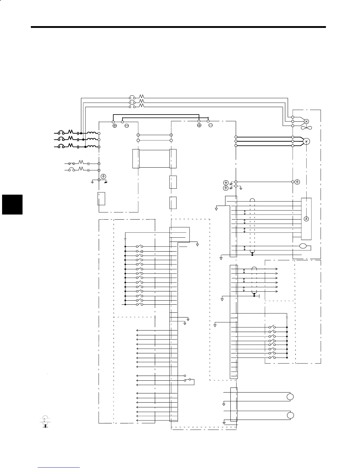
As shown in Fig. 15.31, this is a multi-step speed operation to a maximum of eight speeds using internal
speed settings by changing the digital speed reference settings. This method is effective when performing
operations by repeating speed patterns that have been set beforehand, such as transfer machines and other
special hole-boring equipment. The speed references are set internally, so there is no effect from speed
reference offset and noise. For multi-step speed operations, select internal speed settings using the control
constant C1-37 (SEL2) settings. For details, refer to 4.3 Using a 12-bit Digital Speed Reference.
3MCCB
Special busbar
R
S
T
1MCCB
1MC L
P/ N/
VS−656MR5
R/L1
S/L2
T/L3
P1
N1
5CN
P1
N1
51CN
VS−626M5
1-phase
200 VAC
r
t
2MCCB
2MC
A1/r
A2/t
Not used
1CN
P/
N/
Flat cable
3CN
P1N1 power supply
cable
Not used
52CN
Motor
Cooling fan
U
V
IM
2CN
+5V
0V
4,5,6
1,2,3
THSA
THSB
SS
8
7
9
1
2
3
4
5
6
7
8
9
11
12
10
PG
TS
P
PA
:PA
PB
:
PB
PLC
:
PLC
16
17
18
19
14
15
P
P
P
TLL(INC)
SSC(SV)
19,20,21
22,23
24,25
EXTCOM0*
2
24VCOM
0VCOM
Output Module
*
3
6CN
6
7
8
9
10
11
12
RDY
EMG
FWD
REV
TLH
13
14
5
15
16
17
18
RST
CHW
DAS
PPI
ORT
LGR
MGR
33
34
35
ZSPD
36
37
38
39
40
42
TDET
TLE
ORG
ORE
CHWE
COM1
SDET
AGR
43
44
45
FLT
26
27
28
29
FC0
FC1
FC2
FC3
30
COM2
I/O Card
P
3-phase
200 VAC*
1
41
46
FLTL
TALM
W
Z1
Z2
Z3
External 24 V
power supply
Input Module
LM
SM
Speedometer
Load meter
Encoder Interface
PAO
:PAO
PBO
:PBO
PLCO
:PLCO
13
14
15
16
11
12
SS
17
1CN
P
P
P
Output module
External 24 V
power supply
U/T1
V/T2
W/T3
Digital Operator
(optional)
6CN
SM
47
0V
48
LM
50
0V
49
D1
D2
D3
D4
D5
D6
19
20
21
22
23
24
D7
25
0VCOM
33
24VCOM
32
EXTCOM
31
D8
D9
D10
D11
26
27
28
29
D12
30
3
4
2
SCOM
0V
SS
3-phase
200 VAC*
1
(Ground to 100 Ω
or less.)
indicates shielded twisted-
pair cable.
*1 400-V class: 3-phase 400 VAC
*2 EXTCOM0 on 6CN and EXTCOM
on 1CN are isolated internally.
*3 Connection when sequence input
common is an external common.
(Ground to 100 Ω
or less.)
MCCB: Molded Case Circuit Breaker
MC: Magnetic Contactor
L: AC reactor
PC
PC
*
2
*
3
Fig 15.31 Multi-step Speed Operation Using Internal Speed Settings
15
 Loading...


