3.3 Wiring Main Circuit Terminals
3 -19
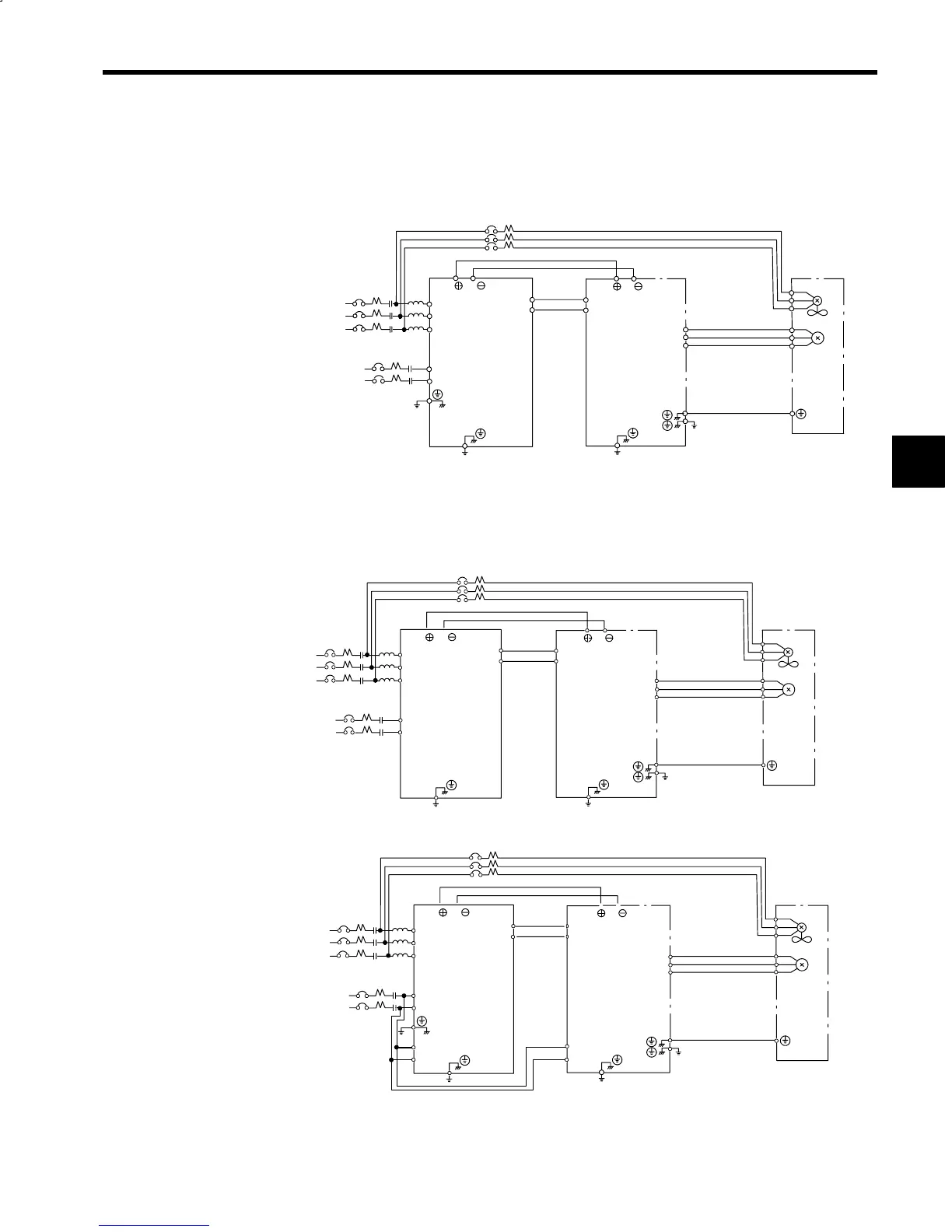
3.3.4 Main Circuit Connection Diagrams
The following diagrams show the main circuit connections.
J
200 V Class External Heatsink Cooling Type
3-phase
200 VAC
Single-phase
200 VAC
Converter (VS-656MR5)
CIMR-MR5j23P75 to 20375
Motor
Cooling fan
Inverter (VS-626M5)
CIMR-M5j23P75 to 20375
R
S
T
r
t
R/L1
S/L2
T/L3
A1/r
A2/t
(Note)
VS−656MR5
P/ N/
VS−626M5
P/ N/
P1
N1
P1
N1
U/T1
V/T2
W/T3
Z1
Z2
Z3
IM
U
V
W
3-phase
200 VAC
Note: No ground terminals are provided on the 23P7 through 27P5 models.
Fig 3.9 Main Circuit Connections for 200 V Class External Heatsink Cooling Type
J 200 V Class Open Chassis Type
Converter (VS-656MR5)
CIMR-MR5j23P70 to 27P50
Inverter (VS-626M5)
CIMR-M5j23P70 to 27P50
R
S
T
r
t
R/L1
S/L2
T/L3
A1/r
A2/t
VS−656MR5
P/ N/
VS−626M5
P/ N/
P1
N1
P1
N1
U/T1
V/T2
W/T3
Z1
Z2
Z3
IM
U
V
W
3-phase
200 VAC
Single-phase
200 VAC
Motor
Cooling fan
3-phase
200 VAC
Converter (VS-656MR5)
CIMR-MR5j20110 to 20370
Inverter (VS-626M5)
CIMR-M5j20110 to 20370
R
S
T
r
t
R/L1
S/L2
T/L3
A1/r
A2/t
VS−656MR5
P/ N/
VS−626M5
P/ N/
P1
N1
P1
N1
U/T1
V/T2
W/T3
Z1
Z2
Z3
IM
U
V
W
A12/r2
A22/t2
A11/r1
A21/t1
3-phase
200 VAC
Single-phase
200 VAC
Motor
Cooling fan
3-phase
200 VAC
Fig 3.10 Main Circuit Connections for 200 V Class Open Chassis Type
3
 Loading...


