Specifications
14.3.2 Molded Case Circuit Breaker and Magnetic Contactor
14 -46
14.3.2 Molded Case Circuit Breaker and Magnetic Contactor
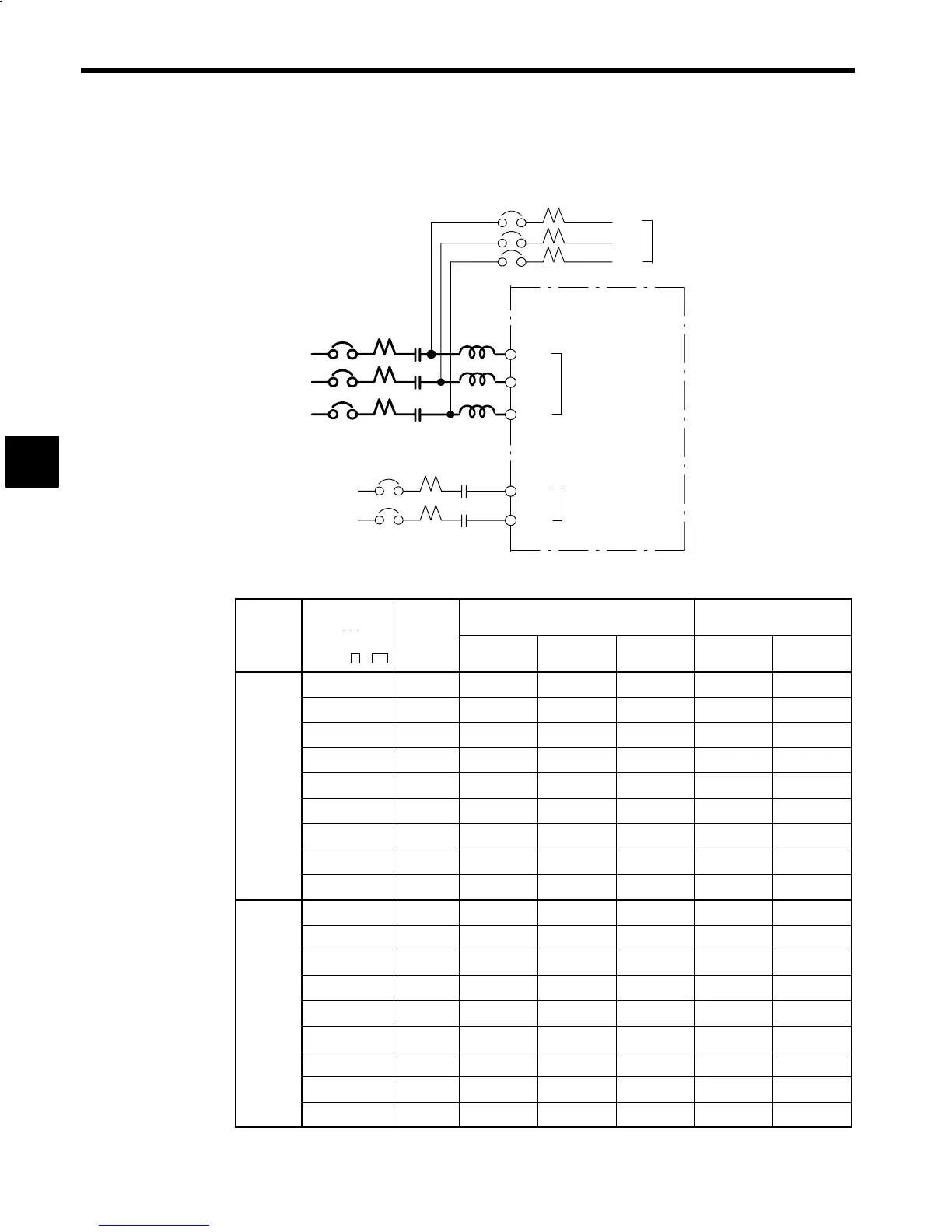
An example of the molded case circuit breaker and magnetic contactor wiring is shown below.
3MCCB
R1
S1
T1
200 VAC*
R
1MCCB
S
T
3-Phase
Single-phase
1MC
2MCCB 2MC
r
t
R/L1
S/L2
T/L3
A1/r
A2/t
VS-656MR5
To Motor Cooling Fan
Main Circuit Power
Supply Input
Control Power
Supply Input
200 VAC
L
*: For 400 V Class, 3-phase 400 VAC.
Select MCCB and MC from the table below according to Converter (VS-656MR5) model.
Voltage
Converter
Model
Power
MCCB Rated Current (A) MC Rated Current (A)
CIMR-
MR5
:
apacity
(kVA)
1MCCB 2MCCB 3MCCB 1MC 2MC
23P7 7 30 3 3 20 3
25P5 9 40 3 3 30 3
27P5 12 50 3 3 40 3
2011 19 75 3 3 60 3
200 V
Class
2015 24 100 3 3 75 3
2018 30 125 3 3 100 3
2022 36 150 3 3 125 3
2030 48 175 3 3 150 3
2037 60 250 3 3 200 3
45P5 9 20 3 2 15 3
47P5 12 25 3 2 20 3
4011 19 40 3 2 30 3
4015 24 50 3 2 40 3
400 V
Class
4018 30 60 3 2 50 3
4022 36 75 3 2 60 3
4030 48 100 3 2 80 3
4037 60 125 3 2 100 3
4045 72 150 3 2 125 3
* A: For stand-alone drive system N: for NC system
14
 Loading...


