3.4 Wiring Control Circuit Signals
3 -31
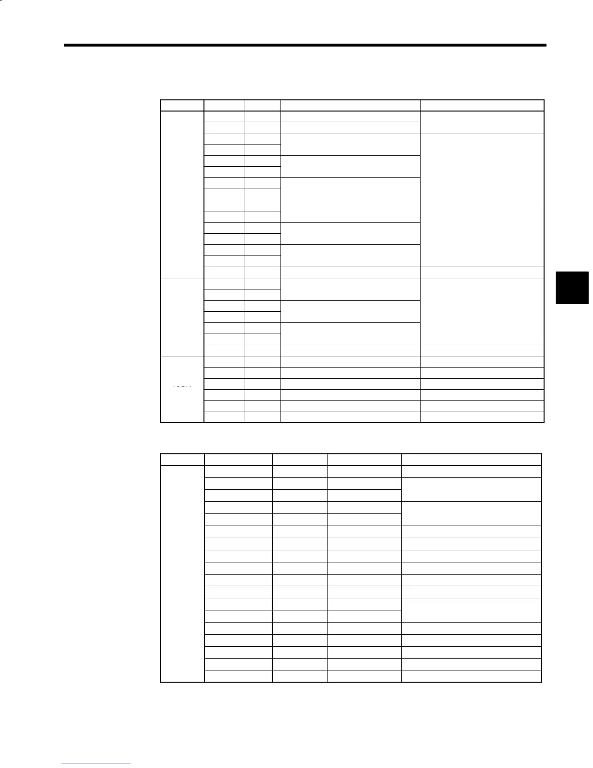
Table 3.14 Control Circuit Signals (8CN, 9CN, 10CN)
Connector Signal No. Function Signal Level
+5V 4, 5, 6 +5V power supply for encoder
+5V
0V 1, 2, 3 Encoder power supply 0 V
Load current: 350mA or less
CPA 9
*CPA 11
−
CPB 12
RS-422A specification
*CPB 13
−
Line receiver
CPC 7
+5 V
8CN
*CPC 8
−
(option)
SPA 16
*SPA 17
Encoder phase A signal input
SPB 18
R
-
spec
cat
on
*SPB 19
Encoder phase B signal input
Line receiver
SPC 14
+5 V
*SPC 15
Encoder phase C signal input
SS 20 Shield (0V) −
SPAO 4
*SPAO 5
Encoder phase A signal output
SPBO 6
R
-
spec
cat
on
9CN
*SPBO 7
Encoder phase B signal output
Line driver
(option)
SPCO 2
+5 V
*SPCO 3
Encoder phase C signal output
SS 1 Shield (0V) −
SIG+ 13 Magnetic sensor signal + −
SIG− 14 Magnetic sensor signal − −
10CN
+15V 12 +15V power supply for magnetic sensor +15V Load current: 100mA or less
(option)
+12V 10 +12V power supply for magnetic sensor +12V Load current: 50mA or less
0V 3, 5 Magnetic sensor power supply 0V −
SS 1 Shield (0V) −
Table 3.15 Control Circuit Signals (51CN, 52CN, 5CN)
Connector Signal No. (51CN) No. (52CN, 5CN) Function
0V 1, 2 1, 2 0V
BAT− 3 4
BAT+ 5 6
−
S 4 3
*S 6 5
−
0V 7to14 7to14 0V
+24V
*1
15 to 22 15 to 22 +24V power supply
AXRUN 23 24 Inverter (servo) running
51CN
CONRST 24 23 Fault reset
52CN
CONRDY 25 26 Converter ready
5CN
CONFLT 26 25 Converter fault
ALM±
*2
29 30
ALMC
*2
27 28
Inverter (servo) fault
ESP0
*2
31 32 Inverter emergency stop
ESP1 28 27 −
/EXT2 30 29 −
/EXT1 32 31 −
+24VIN
*2
34 33 +24V power supply input
* 1. The 24 V power supply is output only for M5N models for NC systems.
* 2. These signals are used only for M5N models for NC systems.
3
 Loading...


