Specifications
14.2.2 Configuration
14 -18
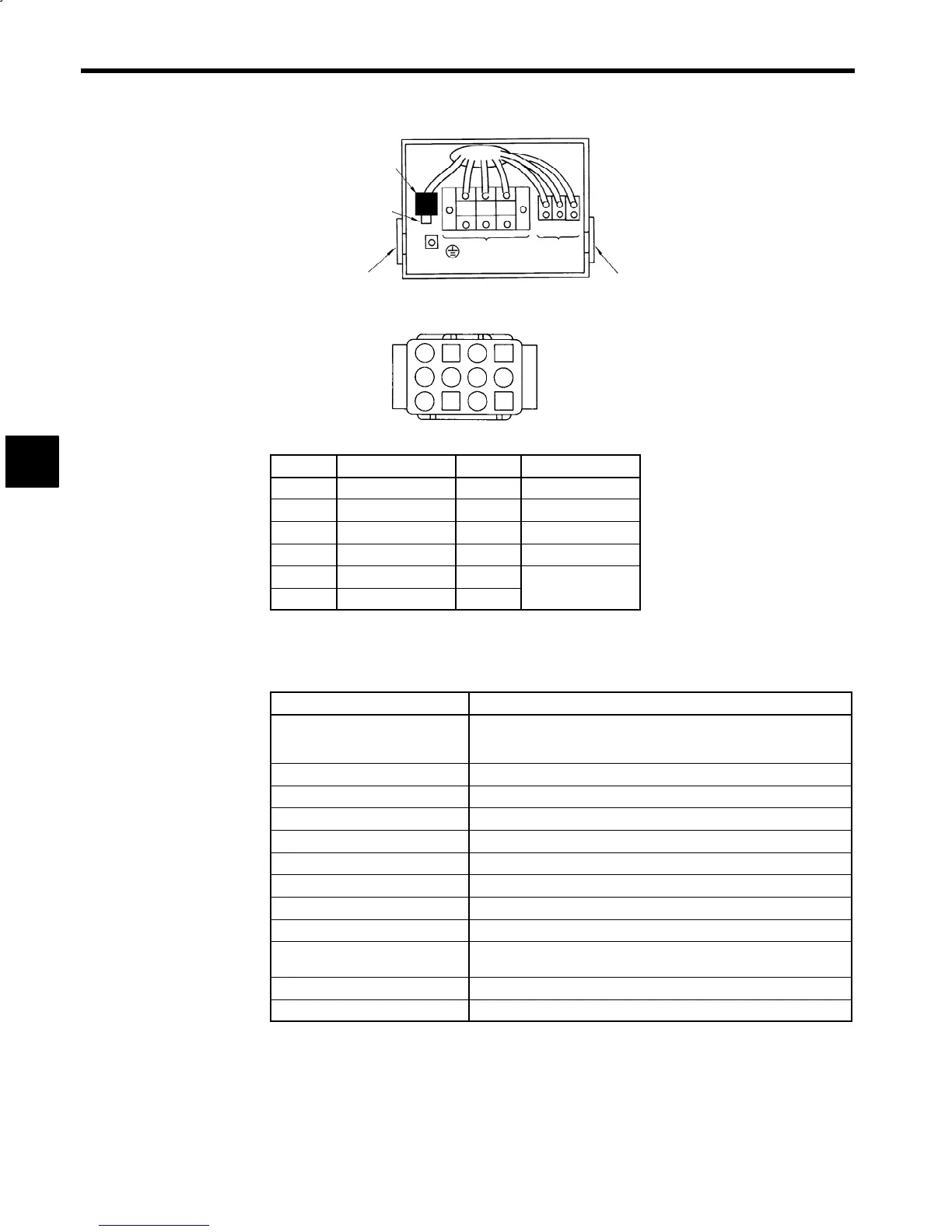
Encoder
board
Encoder
connector
Cable connector
Main circuit
terminals
Fan power
supply ter-
minals
Cable connector
Z1 Z2 Z3
UVW
Fig 14.7 Terminal and Connector Arrangement
1
2
34
5
6
7
8
9
10
11
12
EL Connector (ELR-12V)
Number
Terminal Number Terminal
1
5 VDC
7
PC
2
0V
8
:
PC
3
PA
9
FG (Frame Ground)
4
:
PA
10
SS (Shield)
5
PB
11
TS
6
:
PB
12
Fig 14.8 Encoder Connector
The common motor specifications are shown in the following table.
Table 14.13 Common Motor Specifications
Isolation F type
Cooling Fan
Fan motor: Thermostat (auto resetting)
3-phase 200 V 50/60 Hz, 220 V 50/60 Hz, 230 V 60 Hz,
400 V 50/60 Hz, 440 V 50/60 Hz, 460 V 60 Hz
Overheating Protection
NTC Thermistor
Detector
Magnetic field encoder
Mounting Direction
Output shaft can be between horizontal to vertically down.
Bearing Lubrication
Grease
Color
Munsell N1.5
Ambient Temperature
0°Cto40°C (32°F to 104°F)
Humidity
95% max. (with no condensation)
Elevation
1000 m (3281 ft) max.
Insulation Voltage Resistance
1500 VAC for 1 min. (200 V Series)
1800 VAC for 1 min. (400 V Series)
Insulation Resistance
500 VDC, 10 MΩ min.
Conforming Standards
JIS, JEC
14
 Loading...


