Specifications
14.3.3 Magnetic Contactor Specifications for Winding Selection
14 -48
J
Terminal Descriptions
Table 14.20 Terminal Name and Operation Status
Terminal Name Operation Status
13−14
Selection signal
+24 V (Low-speed
winding)
0 V (High-speed
winding)
1−2
3−4
5−6
Main contact: 3NC Open Closed
7−8
9−10
11−12
Main contact: 3NO Closed Open
15−16
Auxiliary contact: 1NO Open Closed
17−18
200 V power supply − −
12
78
34
910
56
11 12
(a) HV− AP4 (Standard)
12
78
34
910
56
11 12
(b) HV− BP4 (IPM Motor)
Fig 14.17 Main Circuit Contact Configuration
J
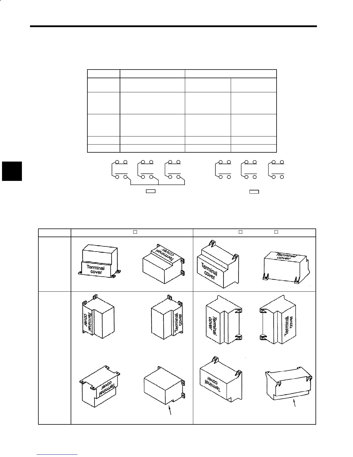
Mounting Orientations
Refer to the following table for mounting orientations.
Mounting HV-75 P4 HV-150 P4 and HV-200 P4
Possible
f
f
Not Possible
×
Terminal
cover
×
Terminal
cover
14
 Loading...


