Signals
OUTPUT IN (Output control input)
This pin receives output control signals. When these signals are received, the GS200
performs the same operation as if its OUTPUT key had been pressed. When a falling
edge is received, the GS200 turns output on. When a rising edge is received, the GS200
turns output off.
OUTPUT OUT (Output control output)
This pin transmits the output state. A high-level signal if the output is off and a low-level
signal if the output is on.
TRIG IN (Trigger input)
This pin receives the STEP trigger for program execution. When a falling edge is
received, the GS200 performs the same operation as if its STEP key had been pressed.
TRIG OUT (Trigger output)
This pin transmits the TrigBusy signal. A low-level signal upon trigger generation and a
high-level signal upon source operation completion.
READY OUT (Source change completion output)
This pin transmits the source change completion signal (Ready). This is transmitted 10
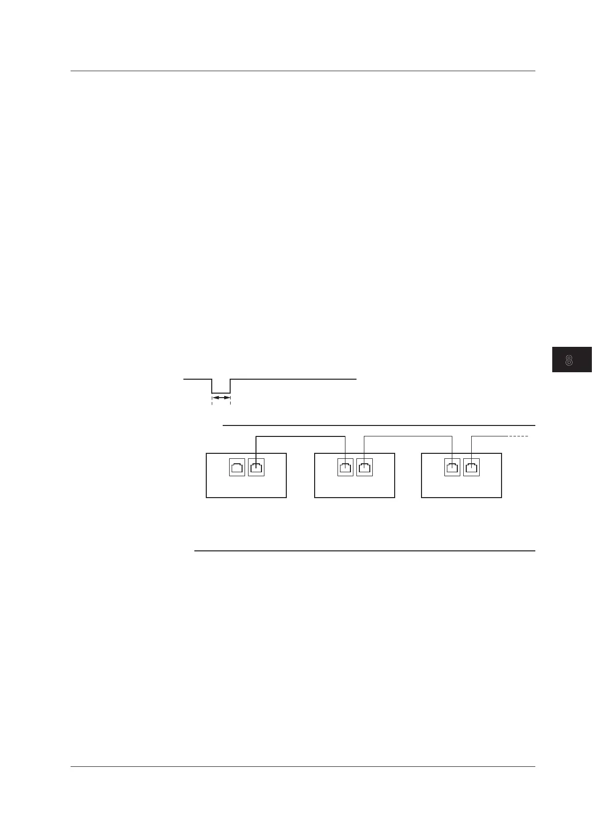
ms after the source level changes as a low pulse with a width of 10
μ
s.
Note
GS210
Master
SYNC
IN OUT
GS210
Slave
SYNC
IN OUT
GS210
Slave
SYNC
IN OUT
The maximum delay from TRIG IN to TRIG OUT is less than or equal to 1
μ
s.
The maximum delay from OUTPUT IN to OUTPUT OUT is less than or equal to 20 ms.
8.2 Using the RJ-11 Connectors (SYNC IN and SYNC OUT) to Perform Synchronous Operation
8-5
IM GS210-01EN
Synchronous Operation
3
2
1
4
5
6
7
8
9
10
11
12
13
14
15
App
Index
 Loading...