2.3 Source
Source Range
Source Range
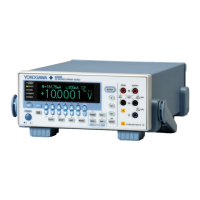
The following figure indicates the range that the GS200 can generate.
200 mA
–32 V 32 V
–200 mA
Current
Voltage
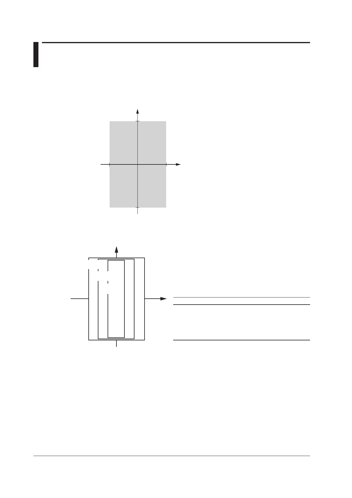
Voltage Source Range (See section 5.2 for the procedure)
The following voltage source ranges are available.
V
I
30 V/200 mA
range
10 V/200 mA
range
1 V/200 mA
range
Range Source Range Resolution Max. Load Current
10 mV ±12.0000 mV 100 nV --------
*
100 mV ±120.000 mV 1 µV --------
*
1 V ±1.20000 V 10 µV ±200 mA
10 V ±12.0000 V 100 µV ±200 mA
30 V ±32.000 V 1 mV ±200 mA
* In voltage source mode’s 10 mV and 100 mV ranges, because the GS200 uses a voltage
divider, the output resistance is approximately 2
Ω
. Therefore, these ranges are not suitable
when the GS200 is connected to a load that allows current to flow (a low-impedance
load). Depending on the load current, the output voltage may decrease. Also, four-terminal
connection does not function for these voltage ranges. You must use the two-terminal
connection instead. Connect a high-impedance load, a load that is sufficiently larger than the
output resistance.
 Loading...