LINK
ACT
ETHERNET
100BASE-TX
IN
OUT USB
SYNC
IN
OUT
100V AC
80 VA MAX
50/60 Hz
FUSE 250 V T 1A
GP-IB
(
IEEE 488
)
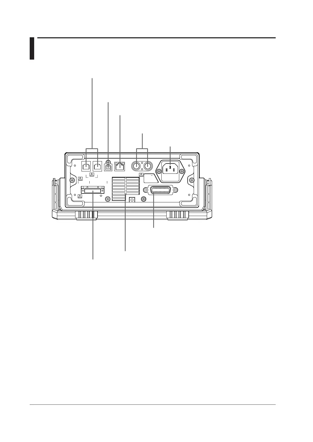
Cooling fan → Section 3.2
USB port
Used to connect the GS200 to a PC that has a USB interface and to access the GS200
as USB storage or to control the GS200 through USB-TMC commands.
→ Sections 4.4 and 10.2
I/O terminals for synchronous operation
Used to connect multiple GS200s and perform synchronous operation. → Section 8.2
Ethernet port
Used to connect the GS200 to a network. → Section 11.2
BNC I/O terminals
Used to receive and transmit trigger, output state, and source
change completion signals. → Section 8.1
Power inlet
Connects to a power supply → Section 3.3
GP-IB connector
Used when controlling the GS200 with commands
through the GP-IB interface. → Section 12.2
Output terminal (only on the GS211)
Used to connect the DUT cable. → Sections 3.5, 3.6, 4.2, and 4.3
*
 Loading...