8.2 Using the RJ-11 Connectors (SYNC IN and
SYNC OUT) to Perform Synchronous Operation
If you connect the I/O terminals for synchronous operation on the rear panel of multiple
GS200s, you can operate them in sync.
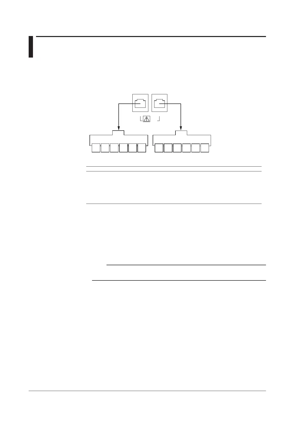
I/O Terminals for Synchronous Operation
There are two RJ-11 connectors, one for input and another for output.
6
NC
5
NC
4
GND
3
TRIG
IN
2
NC
1
OUTPUT
IN
SYNC IN
6
*
5
READY
OUT
4
GND
3
TRIG
OUT
2
NC
1
OUTPUT
OUT
SYNC OUT
IN OUT
SYNC
Synchronous
input
Synchronous
output
Pinout
Pin No. SYNC IN (Synchronous Input) SYNC OUT (Synchronous Output)
1 OUTPUT IN (output control input) OUTPUT OUT (output control output)
2 NC NC
3 TRIG IN (trigger input) TRIG OUT (trigger output)
4 GND GND
5 NC READY OUT (source change completion output)
6 NC *
* This pin is used for servicing the GS200. Do not use it.
Connecting the GS200s
Use a synchronous operation cable (sold separately; 758960; 6-wire) to connect two
GS200s. You can make synchronous operation possible by connecting the synchronous
operation output of a higher level GS200 to the synchronous operation input of a lower
level GS200.
Note
Do not use other commercially available cables. Only use the synchronous operation cable
described above to connect GS200s.
 Loading...