Z8 Microcontrollers
Serial I/O ZiLOG
9-2 UM001601-0803
Configuration of the UART is controlled by the Port 3 Mode
Register (P3M) located at address F7H. The Z8 always transmits
eight bits between the start and stop bits (eight Data Bits or seven
Data Bits and one Parity Bit). Odd parity generation and detec
-
tion is supported.
The SIO Register and its associated Mode Control Registers are
mapped into the Standard Z8 Register File as shown in Table 9-
1. The organization allows the software to access the UART as
general-purpose registers, eliminating the need for special in
-
structions.
9.2 UART BIT-RATE GENERATION
When Port 3 Mode Register bit 6 is set to 1, the UART is enabled
and T0 automatically becomes the bit rate generator (Figure 9-
2). The end-of-count signal of T0 no longer generates Interrupt
Request IRQ4. Instead, the signal is used as the input to the di
-
vide-by-16 counters (one each for the receiver and the transmit-
ter) that clock the data stream.
The divide chain that generates the bit rate is shown in Figure 9-
3. The bit rate is given by the following equation:
Bit Rate = XTAL Frequency/(2 x 4 x p x t x 16)
where p and t are the initial values in Prescaler0 and
Counter/Timer0, respectively. The final divide-by-16 is required
since T0 runs at 16 times the bit rate in order to synchronize on
the incoming data.
To configure the Z8 for a specific bit rate, appropriate values as
determined by the above equation must be loaded into registers
PRE0
(F5H) and T0 (F4H). PRE0 also controls the counting mode for
T0 and should therefore be set to the Continuous Mode (D0 = 1).
Tab le 9-1. UART Register Map
Register Hex
Name Identifier Address
Port 3 Mode P3M F7
T0 Prescaler PRE0 F5
Timer/Counter0 T0 F4
Timer Mode TMR F1
UART SIO F0
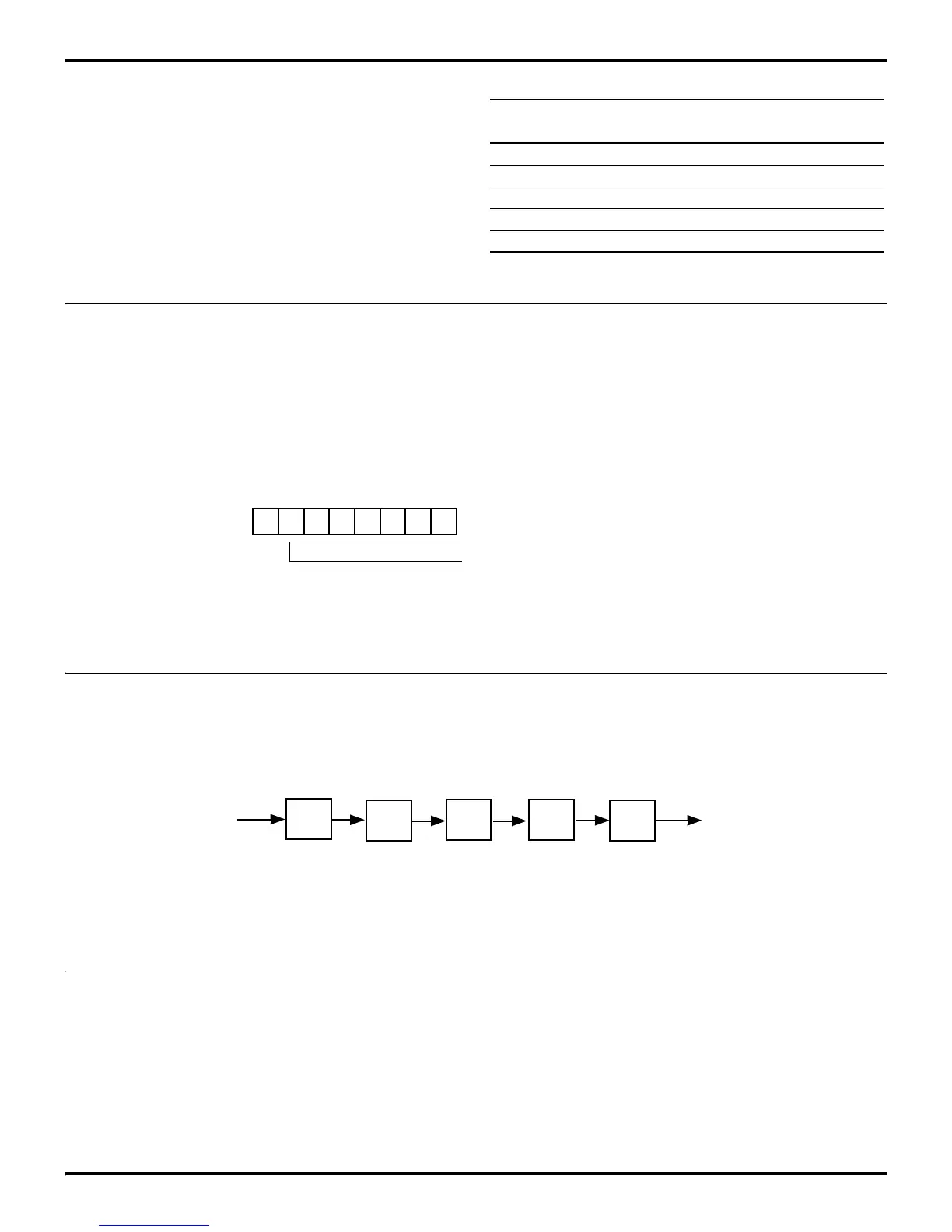
Figure 9-2. Port 3 Mode Register (P3M) and Bit-Rate Generation
D7 D6 D5 D4 D3 D2 D1 D0
(Write-Only)
Port 3 Mode Register (P3M)
Register F7H
0 P30 Input and P37 = Output
1 P30 Serial In and P37 = Serial Out
Figure 9-3. Bit Rate Divide Chain
P
t
÷16
Bit Rate
÷4
÷2
Clock
PRE0
T0
f
XTAL

 Loading...
