Z8 Microcontrollers
Counter/Timers ZiLOG
6-10 UM001601-0803
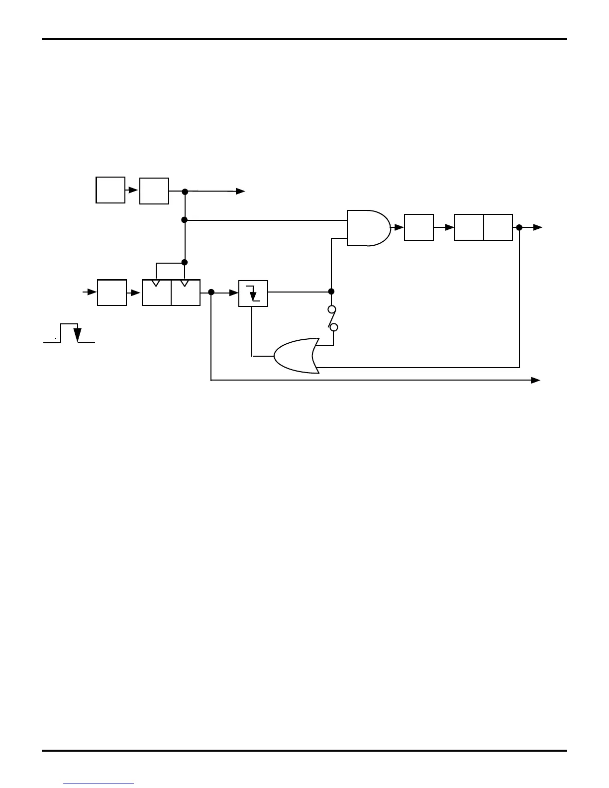
6.5.3 Triggered Input Mode
The T
IN
Triggered Input Mode (TMR bits 5 and 4 are set to 1 and
0, respectively) causes T1 to start counting as the result of an ex
-
ternal event (Figure 6-17). T1 is then loaded and clocked by the
internal timer clock following the first High-to-Low transition
on the T
IN
input. Subsequent T
IN
transitions do not affect T1. In
the Single-Pass Mode, the Enable bit is reset whenever T1 reach
-
es its end-of-count. Further T
IN
transitions will have no effect on
T1 until software sets the Enable Count bit again. In Continuous
mode, once T1 is triggered counting continues until software re
-
sets the Enable Count bit. Interrupt request IRQ5 is generated
when T1 reaches its end-of-count.
Figure 6-17. Triggered Clock Mode
OSC
÷2
÷4
D D
PRE1
TMR
P3
1
T1
IRQ
2
T
IN
IRQ
5
Trigger
D
5
- D
4
= 11
Internal
TMR
D
5
= 1
Clock
Edge
Trigger

 Loading...
