Z8 Microcontrollers
I/O Ports ZiLOG
5-12 UM001601-0803
5.4.2 Read/Write Operations
Port 2 is accessed as General-Purpose Register P2 (02H). Port 2
is written by specifying P2 as an instruction’s destination regis
-
ter. Writing to Port 2 causes data to be stored in the output reg-
ister of Port 2, and reflected externally on any bit configured as
an output.
Port 2 is read by specifying P2 as the source register of an in-
struction. When an output bit is read, data on the external
pin is returned. Under normal loading conditions, this is equiva-
lent to reading the output register. However, if a bit of Port 2 is
defined as an open-drain output, the data returned is the value
forced on the output pin by the external system. This may not be
the same as the data in the output register. Reading input bits of
Port 2 also returns data on the external pins. However, inputs un
-
der handshake control return data latched into the input register
via the input strobe.
5.4.3 Handshake Operation
Port 2 can be placed under handshake control by programming
bit 6 in the Port 3 Mode Register (Figure 5-15). In this configu
-
ration, Port 3 lines P31 and P36 are used as the handshake con-
trol lines DAV2 and RDY2 for input handshake, or RDY2 and
DAV2 for output handshake.
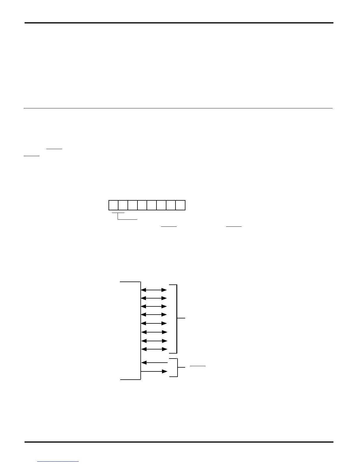
Handshake direction is determined by the configuration (input or
output) assigned to bit 7 of Port 2. Only those bits with the same
configuration as P27 will be under handshake control. Figure 5-
16 illustrates bit lines of Port 2 and the associated handshake
lines of Port 3.
Figure 5-15. Port 2 Handshake Configuration
D7 D6 D5 D4 D3 D2 D1 D0
(Write-Only)
Port 3 Mode Register
Register F7H
1 P31 =
DAV2/RDY2 P36 = RDY2/DAV2
0 P31 = Input (T
IN
) P36 = Output (T
OUT
)
Port 2 Handshaking
Figure 5-16. Port 2 Handshaking
Handshake Controls
DAV2 and RDY2
(P3
1
and P3
6
)
P2
7
Port 2 (I/O)
P2
0