Z8 Microcontrollers
ZiLOG I/O Ports
UM001601-0803 5-19
5.6 PORT HANDSHAKE
When Ports 0, 1, and 2 are configured for handshake operation,
a pair of lines from Port 3 are used for handshake controls. The
handshake controls are interlocked to properly time asynchro
-
nous data transfers between the Z8® and a peripheral. One con-
trol line (/DAV) functions as a strobe from the sender to indicate
to the receiver that data is available. The second control line
(RDY) acknowledges receipt of the sender’s data, and indicates
when the receiver is ready to accept another data transfer.
In the input mode, data is latched into the Port’s input register by
the first /DAV signal, and is protected from being overwritten if
additional pulses occur on the /DAV line. This overwrite protec
-
tion is maintained until the port data is read. In the output mode,
data written to the port is not protected and can be overwritten
by the Z8 during the handshake sequence. To avoid losing data,
the software must not overwrite the port until the corresponding
interrupt request indicates that the external device has latched
the data.
The software can always read Port 3 output and input handshake
lines, but cannot write to the output handshake line.
The following is the recommended setup sequence when config-
uring a Port for handshake operation for the first time after a re-
set:
• Load P01M or P2M to configure the port for input/output.
• Load P3 to set the Output Handshake bit to a logic 1.
• Load P3M to select the Handshake Mode for the port.
Once a data transfer begins, the configuration of the handshake
lines should not be changed until the handshake is completed.
Figures 5-23 and 5-24 show detailed operation for the handshake
sequence.
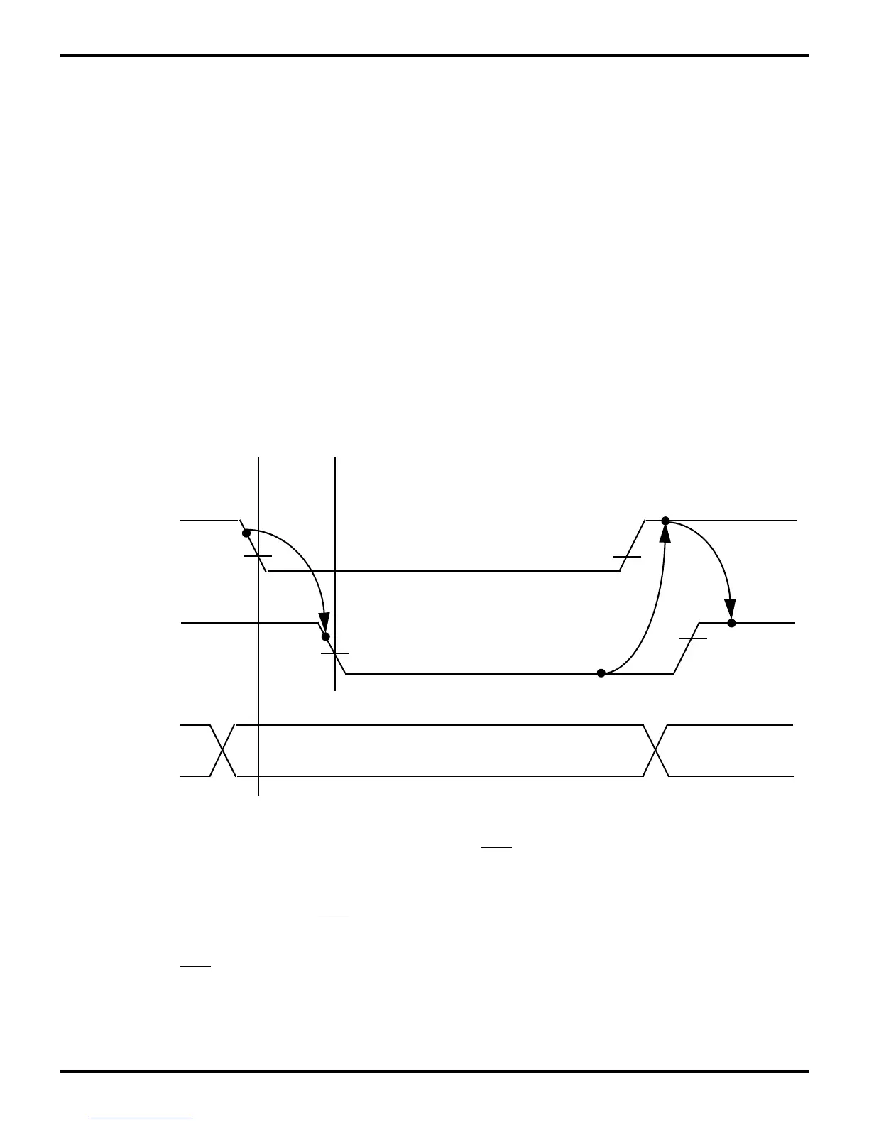
Figure 5-23. Z8 Input Handshake
Valid Data
(Input To Z8)
State 1.
213
45
/DAV
(Output From Z8)
RDY
(Input To Z8)
Data on Port
Port 3 output is High, indicating that the I/O device is ready to accept data.
State 2.
The I/O device puts data on the port and then activates the
DAV input. This causes the data to be latched
.
State 3.
The Z8 forces the Ready (RDY) output Low, signaling to the I/O device that the data has been latched.
State 4.
The I/O device returns the
DAV line High in response to RDY going Low.
State 5.
The Z8 RR software must respond to the interrupt request and read the contents of the port in order for the
into the port input register and generates an interrupt request.
handshake sequence to be completed. The RDY line goes High if and only if the port has been read and
DAV is High. This returns the interface to its initial state.