Z8 Microcontrollers
ZiLOG Counter/Timers
UM001601-0803 6-3
6.3 COUNTER/TIMER OPERATION
Under software control, counter/timers are started and stopped
via the Timer Mode Register (TMR,F1H) bits D
0
-D
3
(Figure 6-
6). Each counter/timer is associated with a Load bit and an En
-
able Count bit.
6.3.1 Load and Enable Count Bits
Setting the Load bit (D
0
for T0 and D
2
for T1) transfers the initial
value in the prescaler and the counter/timer registers into their
respective down-counters. The next internal clock resets bits D
0
and D
2
to 0, readying the Load bit for the next load operation.
New values may be loaded into the down-counters at any time.
If the counter/timer is running, it continues to do so and starts the
count over with the new value. Therefore, the Load bit actually
functions as a software re-trigger.
The counter timers remain at rest as long as the Enable Count
bits are 0. To enable counting, the Enable Count bit (D
1
for T0
and D
3
for T1) must be set to 1. Counting actually starts when
the Enable Count bit is written by an instruction. The first decre
-
ment occurs four internal clock periods after the Enable Count
bit has been set. If T1 is configured to use an external clock, the
first decrement begins on the next clock period. The Load and
Enable Count bits can be set at the same time. For example, us
-
ing the instruction:
OR TMR,#03H
sets both D0 and D1 of the TMR. This loads the initial values of
PRE0 and T0 into their respective counters and starts the count
after the M2T2 machine state after the operand is fetched (Figure
6-7).
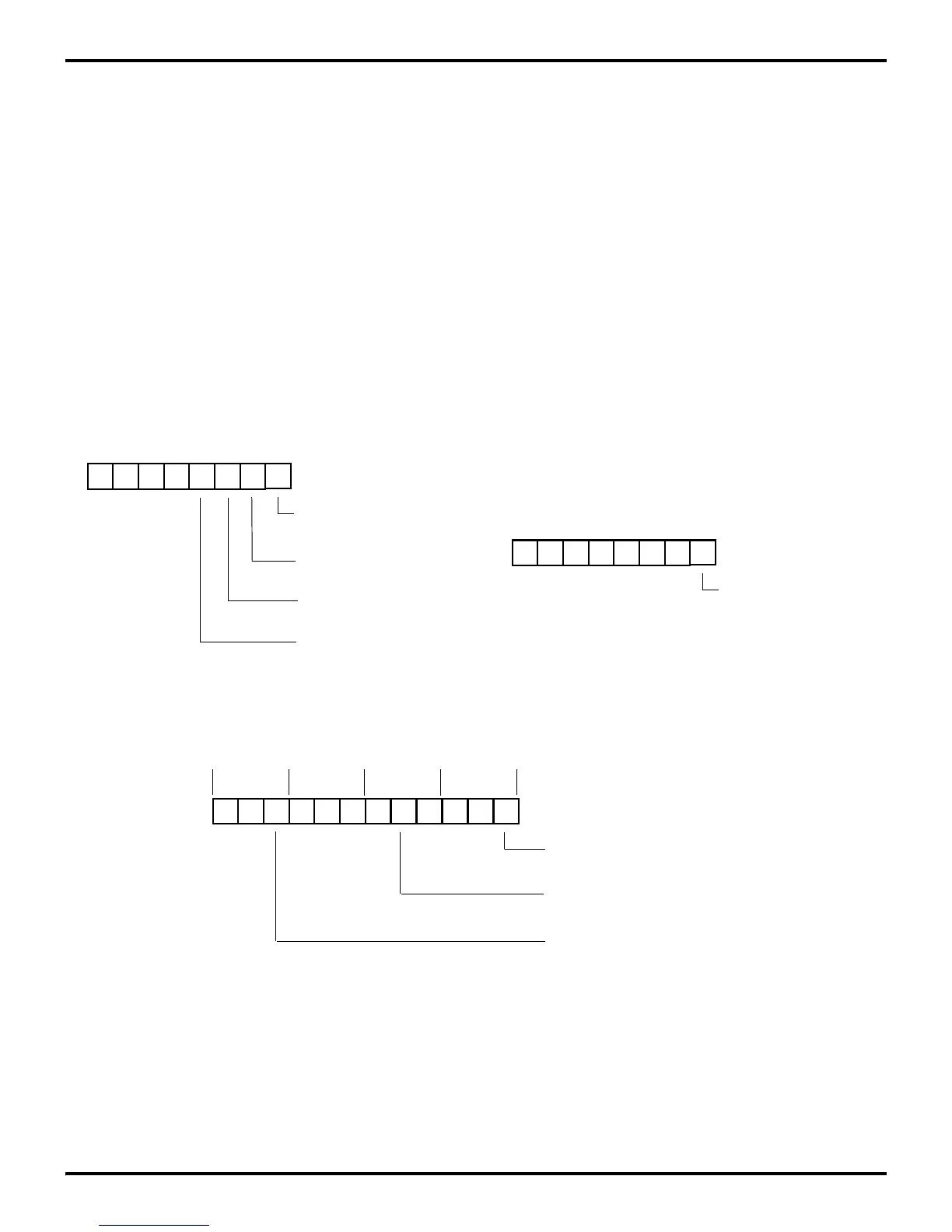
Figure 6-6. Timer Mode Register
D3 D2 D1 D0
(% F1; Read/Write)
0 = Disable T
0
Count
0 = No Function
1 = Load T
0
Timer Mode Register
R241 TMR
1 = Enable T
0
Count
0 = No Function
1 = Load T
1
0 = Disable T
1
Count
1 = Enable T
1
Count
Figure 6-7. Starting The Count
D0
(% F5; Write-Only)
Count Mode
Prescaler 0 Register
R245 PRE0
(% F3; Write-Only)
Prescaler 1 Register
R243 PRE1
0 = T
1
Single Pass
1 = T
1
Modulo-n
Figure 6-8. Counting Modes
T1 T2 T3 T1 T2 T3 T1 T2 T3 T1 T2 T3
TMR is Written, Counter/Timer
First Decrement Occurs
Four Clock Periods Later
is Loaded
#03H is Fetched
M3 M1 M2 Mn

 Loading...
