UM001601-0803 7-1
USER’S MANUAL
CHAPTER 7
INTERRUPTS
7.1 INTRODUCTION
The Z8 MCU
®
allows 6 different interrupts from a variety of
sources; up to four external inputs, the on-chip Counter/Tim
-
er(s), software, and serial I/O peripherals. These interrupts can
be masked and their priorities set by using the Interrupt Mask
and the Interrupt Priority Registers. All six interrupts can be glo
-
bally disabled by resetting the master Interrupt Enable, bit 7 in
the Interrupt Mask Register, with a Disable Interrupt (DI) in
-
struction. Interrupts are globally enabled by setting bit 7 with an
Enable Interrupt (EI) instruction.
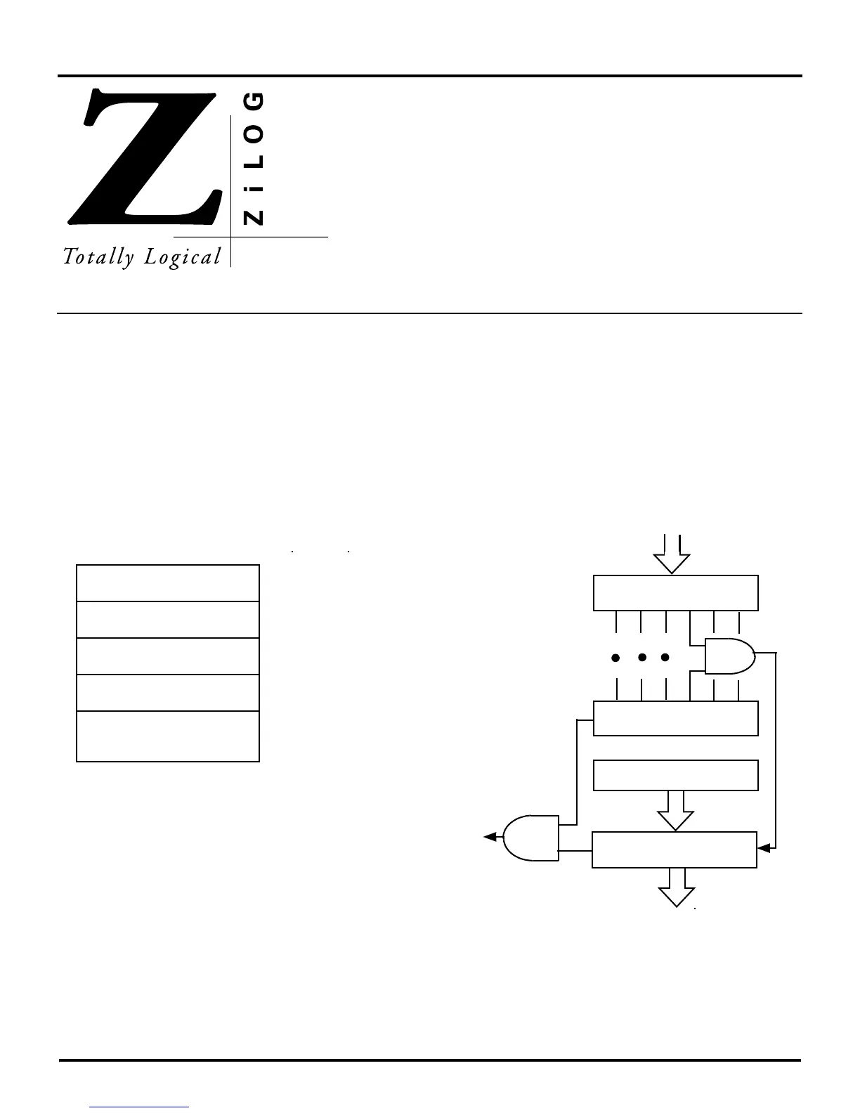
There are three interrupt control registers: the Interrupt Request
Register (IRQ), the Interrupt Mask register (IMR), and the Inter
-
rupt Priority Register (IPR). Figure 7-1 shows addresses and
identifiers for the interrupt control registers. Figure 7-2 is a block
diagram showing the Interrupt Mask and Interrupt Priority logic.
The Z8 MCU family supports both vectored and polled interrupt
handling. Details on vectored and polled interrupts can be found
later in this chapter.
Note: See the selected Z8 MCU's product specification for the
exact interrupt sources supported.
Figure 7-1. Interrupt Control Registers
Register
HEX
Interrupt Mask
Interrupt Request
Interrupt Priority
Identifier
FBH
FAH
F9H
IMR
IRQ
IPR
Figure 7-2. Interrupt Block Diagram
IRQ
IRQ
0
- IRQ
5
Vector Select
Interrupt
Request
IMR
IPR
Priority Logic
6
Global
Interrupt
Enable
6
 Loading...

