Z8 Microcontrollers
ZiLOG External Interface
UM001601-0803 10-3
10.3 EXTERNAL ADDRESSING CONFIGURATION
The minimum bus configuration uses Port 1 as a multiplexed ad-
dress/data port (AD7 - AD0), allowing access to 256 bytes of ex-
ternal memory. In this configuration, the eight low-order bits
(A0 - A7) are multiplexed with the data (D7 - D0).
Port 0 can be programmed to provide either four additional ad-
dress lines (A11- A8), which increases the addressable memory
to 4K bytes, or eight additional address lines (A15 - A8), which
increases the addressable external memory up to 64K bytes. It is
required to add a NOP after configuring Port 0 / Port 1 for exter
-
nal addressing before jumping to external memory execution.
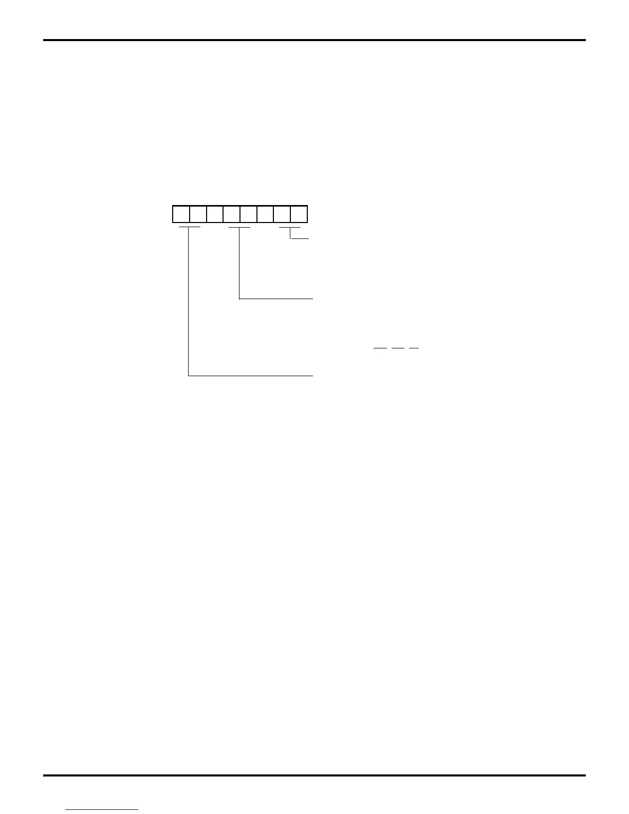
Figure 10-2. External Address Configuration
D7 D6 D5 D4 D3 D2 D1 D0
(Write-Only)
01 = Input
1X = A
8
- A
11
P0
0
- P0
7
Mode
00 = Output
Port 0-1 Mode Register (P01M)
Register F8H (P01M)
01 = Byte Output
P0
4
- P0
7
Mode
00 = Output
01 = Input
1X = A
12
- A
15
10 = AD
0
-AD
7
00 = Byte Output
P
10
- P
17
Mode
A
8
- A
15
, AS, DS, R/W
11 = High Impedance AD
0
- AD
7
,

 Loading...
