Z8 Microcontrollers
Interrupts ZiLOG
7-6 UM001601-0803
7.4 INTERRUPT INITIALIZATION (Continued)
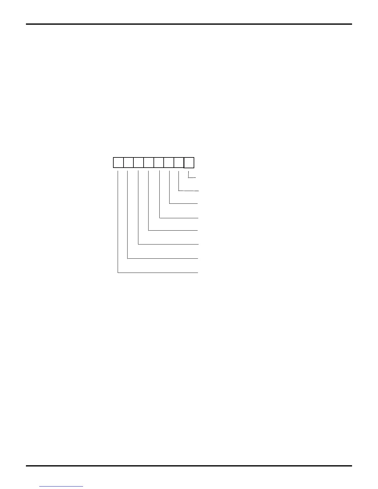
7.4.2 Interrupt Mask Register (IMR) Initialization
IMR individually or globally enables or disables the six interrupt
requests (Figure 7-8). When bit 0 to bit 5 are set to 1, the corre
-
sponding interrupt requests are enabled. Bit 7 is the master en-
able and must be set before any of the individual interrupt re-
quests can be recognized. Resetting bit 7 globally disables all the
interrupt requests. Bit 7 is set and reset by the EI and DI instruc
-
tions. It is automatically reset during an interrupt service routine
and set following the execution of an Interrupt Return (IRET) in
-
struction.
Note: Bit 7 must be reset by the DI instruction before the
contents of the Interrupt Mask Register or the Interrupt Priority
Register are changed except:
• Immediately after a hardware reset.
• Immediately after executing an interrupt service routine and
before IMR bit 7 has been set by any instruction.
Note: The RAM Protect option is selected at ROM mask
submission time or at EPROM program time. If not selected or
not an available option, this bit is reserved and must be 0.
Figure 7-8. Interrupt Mask Register
D7 D6 D5 D4 D3 D2 D1 D0
(Read/Write)
Interrupt Request Register (IMR)
Register FBH
0 = Disables IRQ0
1 = Enables IRQ0
0 = Disables IRQ1
1 = Enables IRQ1
0 = Disables IRQ2
1 = Enables IRQ2
0 = Disables IRQ3
1 = Enables IRQ3
0 = Disables IRQ4
1 = Enables IRQ4
0 = Disables IRQ5
1 = Enables IRQ5
0 = Disables RAM Protect
1 = Enables RAM Protect
0 = Disables Interrupt
1 = Enables Interrupt