Z8 Microcontrollers
ZiLOG Interrupts
UM001601-0803 7-11
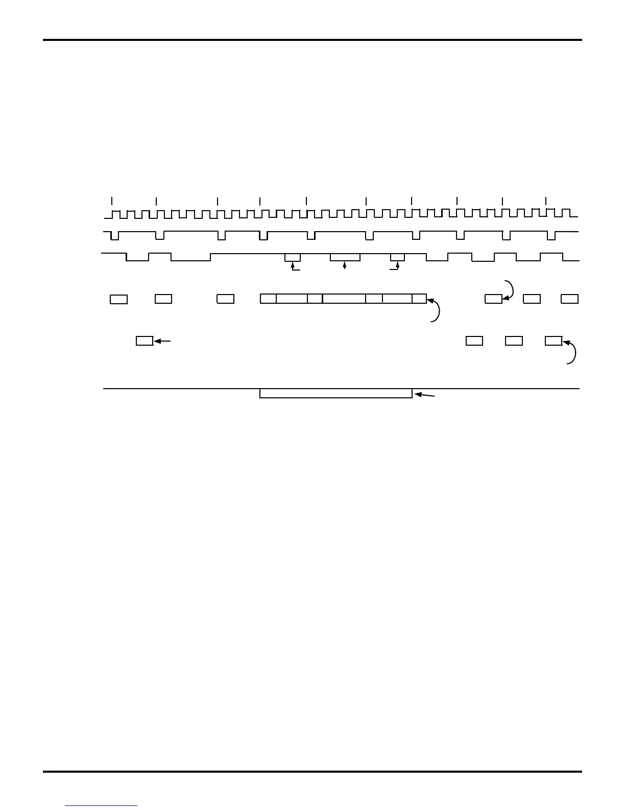
7.6.1 Vectored Interrupt Cycle Timing
The interrupt acknowledge cycle time is 24 internal clock cycles
and is shown in Figure 7-13. In addition, two internal clock cy
-
cles are required for the synchronizing flip-flops. The maximum
interrupt recognition time is equal to the number of clock cycles
required for the longest executing instruction present in the user
program (assumes worst case condition of interrupt sampling,
Figure 7-6, just prior to the interrupt occurrence). To calculate
the worst case interrupt latency (maximum time required from
interrupt generation to fetch of the first instruction of the inter
-
rupt service routine), sum these components:
Worst Case Interrupt Latency ≈ 24 INT CLK (interrupt acknowl-
edge time) + # T
P
C of longest instruction present in the user's ap-
plication program + 2T
P
C (internal synchronization time).
Figure 7-13. Z8 Interrupt Acknowledge Timing
PC
For Stack External Only
PC+1
PC
PCLSP-1
SP-2
PCH SP-3 FLAGS
VECT
VECT+1
Even Vector Address
Odd Vector Address
Op Code (Discarded)
VECTH
VECTL
First Instruction Of Interrupt Service Routine
For Stack External Only
A0-A7 IN
Internal Clock
/AS
/DS
A0-A7 OUT
M3
M1
M2
M1
M2
Stack Push
Fetch
Vector High
Fetch
Vector Low
Stack Push Stack Push
R/W

 Loading...
