Z8 Microcontrollers
Clock ZiLOG
3-6 UM001601-0803
3.5 LC OSCILLATOR
The Z8 oscillator can use a LC network to generate a XTAL
clock (Figure 3-8).
The frequency stays stable over V
CC
and temperature. The oscil-
lation frequency is determined by the equation:
where L is the total inductance including parasitics and C
T
is the
total series capacitance including the parasitics.
Simple series capacitance is calculated using the following equa-
tion:
Sample calculation of capacitance C
1
and C
2
for 5.83 MHz fre-
quency and inductance value of 27 uH:
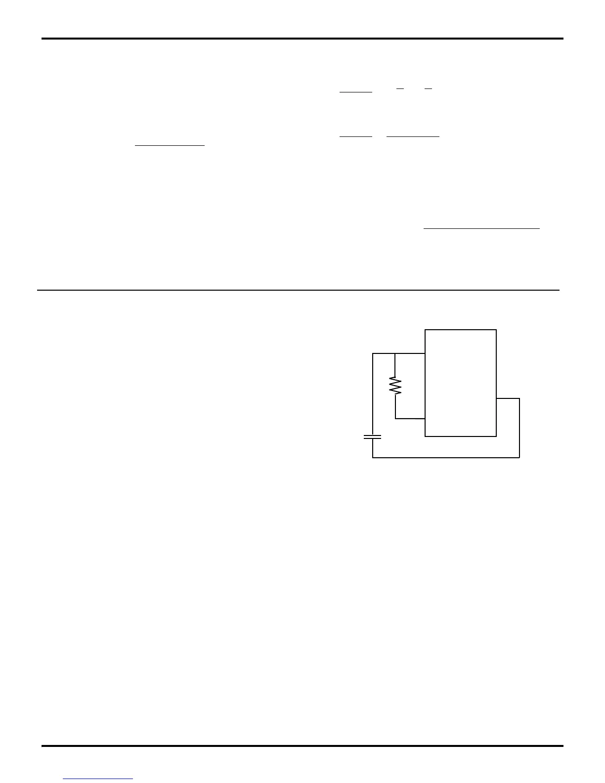
3.6 RC OSCILLATOR
In some cases, the Z8 has a RC oscillator option. Please refer to
the specific product specification for availability. The RC oscil
-
lator requires a resistor across XTAL1 and XTAL2. An addition-
al load capacitor is required from the XTAL1 input to V
SS
pin
(Figure 3-10).
1
Frequency = 2 π (LCT)1/2
1 = 1 + 1
C
T
= C
1
C
2
If C
1
= C
2
1 = 2
C
T
= C
1
C
1
= 2CT
5.83 (10^6) = 1
2π [2.7 (10
-6
) CT] 1/2
CT = 27.6 pf
Thus C
1
= 55.2 pf and C
2
= 55.2 pf.
Figure 3-10. RC Clock
XTAL2
Z8
V
SS
XTAL1
C1
R

 Loading...
