Z8 Microcontrollers
Counter/Timers ZiLOG
6-2 UM001601-0803
Counter/timers 0 and 1 are driven by a timer clock generated by
dividing the internal clock by four. The divide-by-four stage, the
6-bit prescaler, and the 8-bit counter/timer form a synchronous
16-bit divide chain. Counter/timer 1 can also be driven by a ex
-
ternal input (T
IN
) using P31. Port 3 line P36 can serve as a timer
output (T
OUT
) through which T0, T1, or the internal clock can be
output. The timer output will toggle at the end-of-count.
The counter/timer, prescaler, and associated mode registers are
mapped into the register file as shown in Figure 6-2. This allows
the software to treat the counter/timers as general-purpose regis
-
ters, and eliminates the need for special instructions.
6.2 PRESCALERS AND COUNTER/TIMERS
The prescalers, PRE0 (F5H) and PRE1 (F3H), each consist of an
8-bit register and a 6-bit down-counter as shown in Figure 6-1.
The prescaler registers are write-only registers. Reading the
prescalers returns the value FFH. Figures 6-3 and 6-4 show the
prescaler registers.
The six most significant bits (D2-D7) of PRE0 or PRE1 hold the
prescalers count modulo, a value from 1 to 64 decimal. The pres
-
caler registers also contain control bits that specify T0 and T1
counting modes. These bits also indicate whether the clock
source for T
1
is internal or external. These control bits will be
discussed in detail throughout this chapter.
The counter/timer registers, T0 (F4H) and T1 (F2H), each con-
sist of an 8-bit down-counter, a write-only register that holds the
initial count value, and a read-only register that holds the current
count value (Figure 6-1). The initial value can range from 1 to
256 decimal (01H,02H,..,00H). Figure 6-5 illustrates the
counter/timer registers.
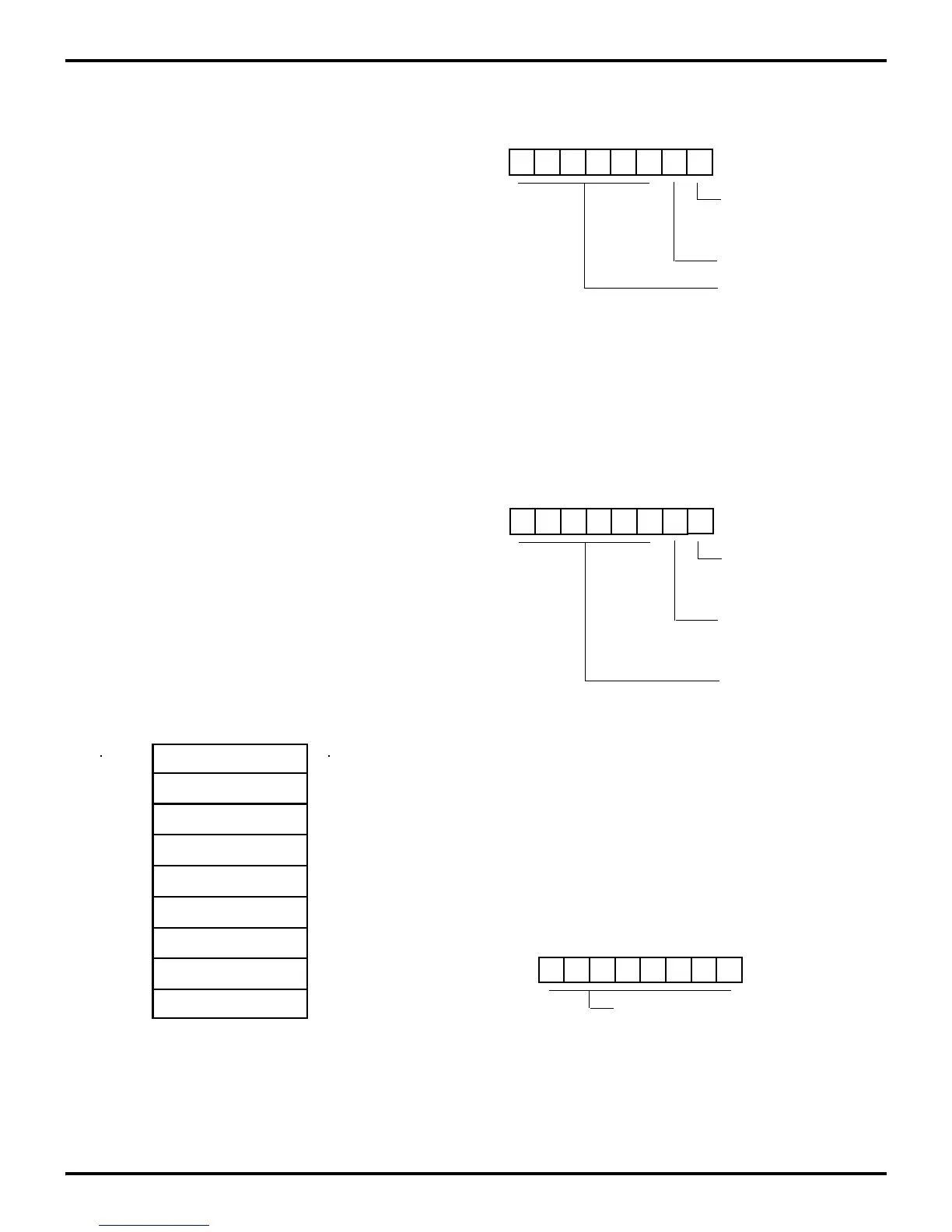
Figure 6-2. Counter/Timer Register Map
HEX Identifiers
T0 Prescaler
F7
Timer/Counter0
Port 3 Mode
T1 Prescaler
Time/Counter1
Timer Mode
F5
F4
F3
F2
F1
DEC
247
245
244
243
242
241
Figure 6-3. Prescaler 0 Register
Figure 6-4. Prescaler 1 Register
Figure 6-5. Counter / Timer 0 and 1 Registers
D7 D6 D5 D4 D3 D2 D1 D0
(%F5; Write-Only)
1 = T
0
Modulo-n
Count Mode
0 = T
0
Single Pass
Prescaler 0 Register
R245 PRE0
01-00 HEX)
Prescaler Modulo
(Range: 1-64 Decimal
Reserved (Must be 0)
U U U U U U 0 0
(%F3; Write-Only)
1 = T
1
Modulo-n
Count Mode
0 = T
1
Single Pass
Prescaler 1 Register
R243 PRE1
01-00 HEX)
Prescaler Modulo
(Range: 1-64 Decimal
Clock Source
0 = T
1
External (T
IN
)
1 = T
1
Internal
D7 D6 D5 D4 D3 D2 D1 D0
(%F4; Write/Read Only)
current value when read
Initial value when written
(Range 1-256 decimal, 01-00 HEX)
Counter/Timer 0 Register
R244 T0
(%F2; Write/Read Only)
Counter/Timer 1 Register
R242 T1
 Loading...

