Z8 Microcontrollers
Interrupts ZiLOG
7-4 UM001601-0803
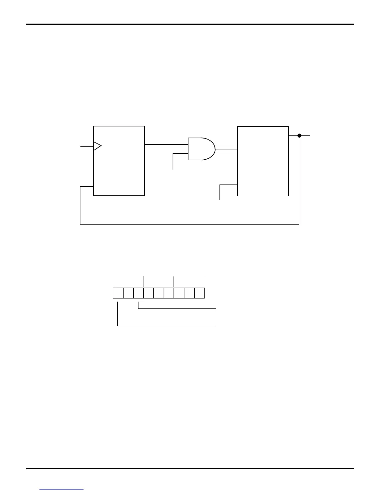
7.3 INTERRUPT REQUEST REGISTER LOGIC AND TIMING
Figure 7-5 shows the logic diagram for the Interrupt Request
(IRQ) Register. The leading edge of the request will set the first
flip-flop, that will remain set until interrupt requests are sam
-
pled.
Requests are sampled internally during the last clock cycle be-
fore an opcode fetch (Figure 7-6). External requests are sampled
two internal clocks earlier, due to the synchronizing flip-flops
shown in Figures 7-3 and 7-4.
At sample time the request is transferred to the second flip-flop
in Figure 7-5, that drives the interrupt mask and priority logic.
When an interrupt cycle occurs, this flip-flop will be reset only
for the highest priority level that is enabled.
The user has direct access to the second flip-flop by reading and
writing the IRQ Register. IRQ is read by specifying it as the
source register of an instruction and written by specifying it as
the destination register.
Figure 7-5. IRQ Register Logic
Q
S
From
To Mask
IRQ
0
- IRQ
5
R
Q
R
Priority
Logic
and
Priority
Logic
Sample
Clock
Figure 7-6. Interrupt Request Timing
T1 T2 T3 T1 T2 T3 T1 T2 T3
External Interrupt
Interrupt Request
Sampled Internally
Request Sampled
Mn M1 M2

 Loading...
