Z8 Microcontrollers
Counter/Timers ZiLOG
6-12 UM001601-0803
6.7 RESET CONDITIONS
After a hardware reset, the counter/timers are disabled and the
contents of the counter/timer and prescaler registers are unde
-
fined. However, the counting modes are configured for Single-
Pass and the T1 clock source is set for external.
T
IN
is set for External Clock mode, and the T
OUT
mode is off.
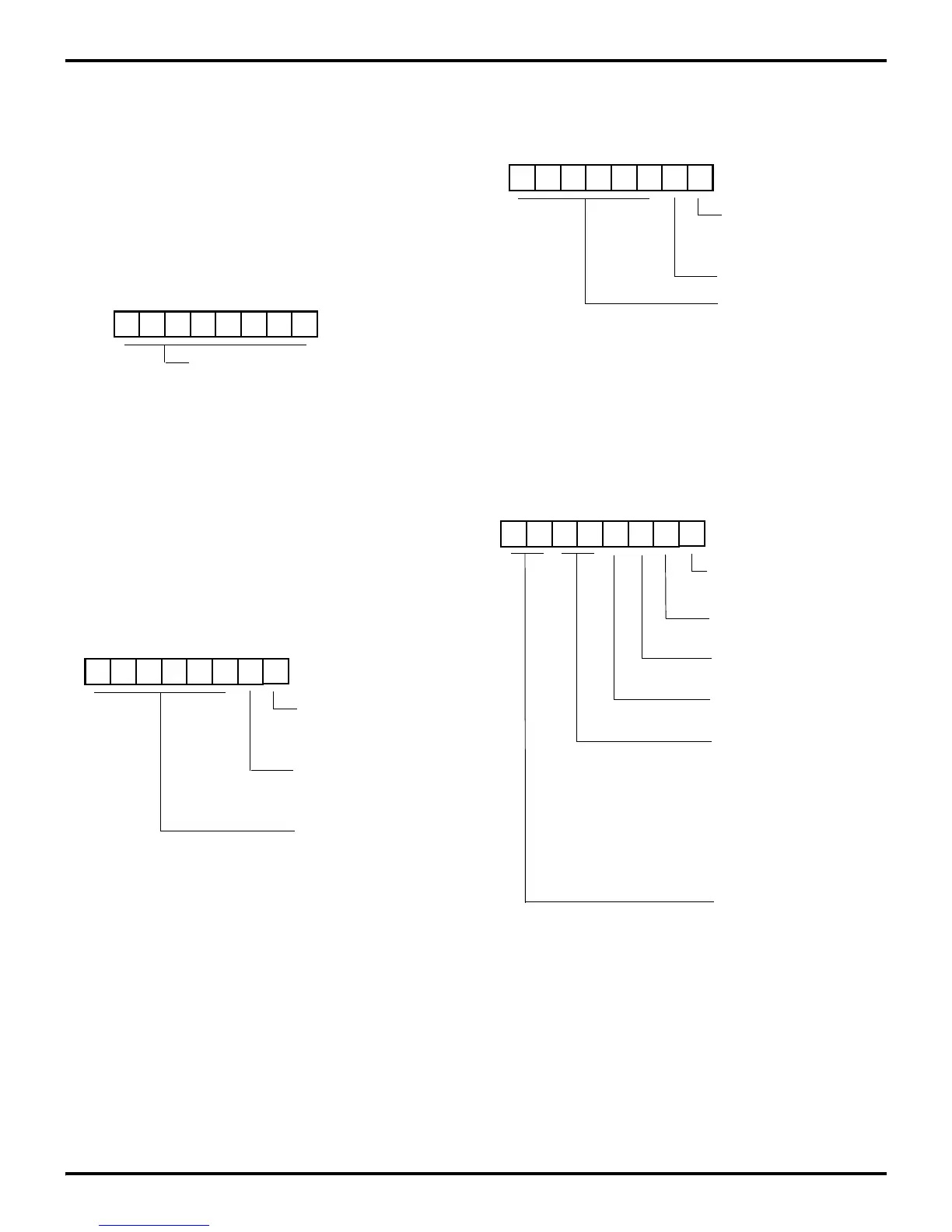
Figures 6-19 through 6-22 show the binary reset values of the
Prescaler, Counter/Timer, and Timer Mode registers.
Figure 6-19. Counter / Timer Reset
Figure 6-20. Prescaler 1 Register Reset
U U U U U U U U
(%F4; Write/Read Only)
current value when read
Initial value when written
(Range 1-256 decimal, 01-00 HEX)
Counter/Timer 0 Register
R244 T0
(%F2; Write/Read Only)
Counter/Timer 1 Register
R242 T1
U U U U U U 0 0
(%F3; Write-Only)
1 = T
1
Modulo-n
Count Mode
0 = T
1
Single Pass
Prescaler 1 Register
R243 PRE1
01-00 HEX)
Prescaler Modulo
(Range: 1-64 Decimal
Clock Source
0 = T
1
External (T
IN
)
1 = T
1
Internal
Figure 6-21. Prescaler 0 Reset
Figure 6-22. Timer Mode Register Reset
U U U U U U U 0
(%F5; Write-Only)
1 = T
0
Modulo-n
Count Mode
0 = T
0
Single Pass
Prescaler 0 Register
R245 PRE0
01-00 HEX)
Prescaler Modulo
(Range: 1-64 Decimal
Reserved (Must be 0)
0 0 0 0 0 0 0 0
(% F1; Read/Write)
0 = Disable T
0
Count
0 = No Function
1 = Load T
0
Timer Mode Register
R241 TMR
1 = Enable T
0
Count
(Retriggerable)
T
OUT
Modes:
(Non-retriggerable)
Trigger Input = 10
T
IN
= Modes:
External Clock Input = 00
Gate Input = 01
0 = No Function
1 = Load T
1
0 = Disable T
1
Count
1 = Enable T
1
Count
T
OUT
OFF = 00
T
0
OUT = 01
T
1
OUT = 10
Internal Clock OUT = 11
Trigger Input = 11