Z8 Microcontrollers
ZiLOG Serial I/O
UM001601-0803 9-5
After a full character has been assembled in the receiver’s buffer,
SIO Register (F0H), Interrupt Request IRQ3 is generated. The
shift clock is stopped and the Shift Register reset to all 1s. The
start bit detection circuitry begins monitoring the data input for
the next start bit. This cycle allows the receiver to synchronize
on the center of the bit time for each incoming character.
9.3.2 Overwrites
Although the receiver is single buffered, it is not protected from
being overwritten, so the software must read the SIO Register
(F0H) within one character time after the interrupt request
(IRQ3). The Z8 does not have a flag to indicate this overrun con
-
dition. If polling is used, the IRQ3 bit in the Interrupt Request
Register must be reset by software.
9.3.3 Framing Errors
Framing error detection is not supported by the receiver hard-
ware, but by responding to the interrupt request within one char-
acter bit time, the software can test for a stop bit on P30. Port 3
bits are always readable, which facilitates break detection. For
example, if a null character is received, testing P30 results in a 0
being read.
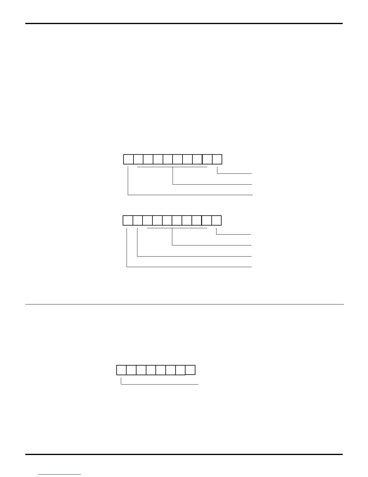
9.3.4 Parity
The data format supported by the receiver must have a start bit,
eight data bits, and at least one stop bit. If parity is on, bit 7 of
the data received will be replaced by a Parity Error Flag. A parity
error sets bit 7 to 1, otherwise, bit D7 is set to 0. Figure 9-7 shows
these data formats.
The Z8
hardware supports odd parity only, that is enabled by
setting the Port 3 Mode Register bit 7 to 1 (Figure 9-8). If even
parity is required, the Parity Mode should be disabled (P3M bit
7 set to 0), and software must calculate the received data’s parity.
Figure 9-7. Receiver Data Formats
SP D7 D6 D5 D4 D3 D2 D1 D0 ST
Eight Data Bits
Start Bit
Start Bit
Seven Data Bits
One Stop Bit
SP P D6 D5 D4 D3 D2 D1 D0 ST
Parity Error Flag
One Stop Bit
Received Data
(No Parity)
Received Data
(With Parity)
Figure 9-8. Port 3 Mode Register (P3M) Parity
D7 D6 D5 D4 D3 D2 D1 D0
(Write-Only)
0 = Parity OFF
1 = Parity ON
Port 3 Mode Register (P3M)
Register F7H

 Loading...
