Z8 Microcontrollers
ZiLOG Counter/Timers
UM001601-0803 6-5
6.4 T
OUT
MODES
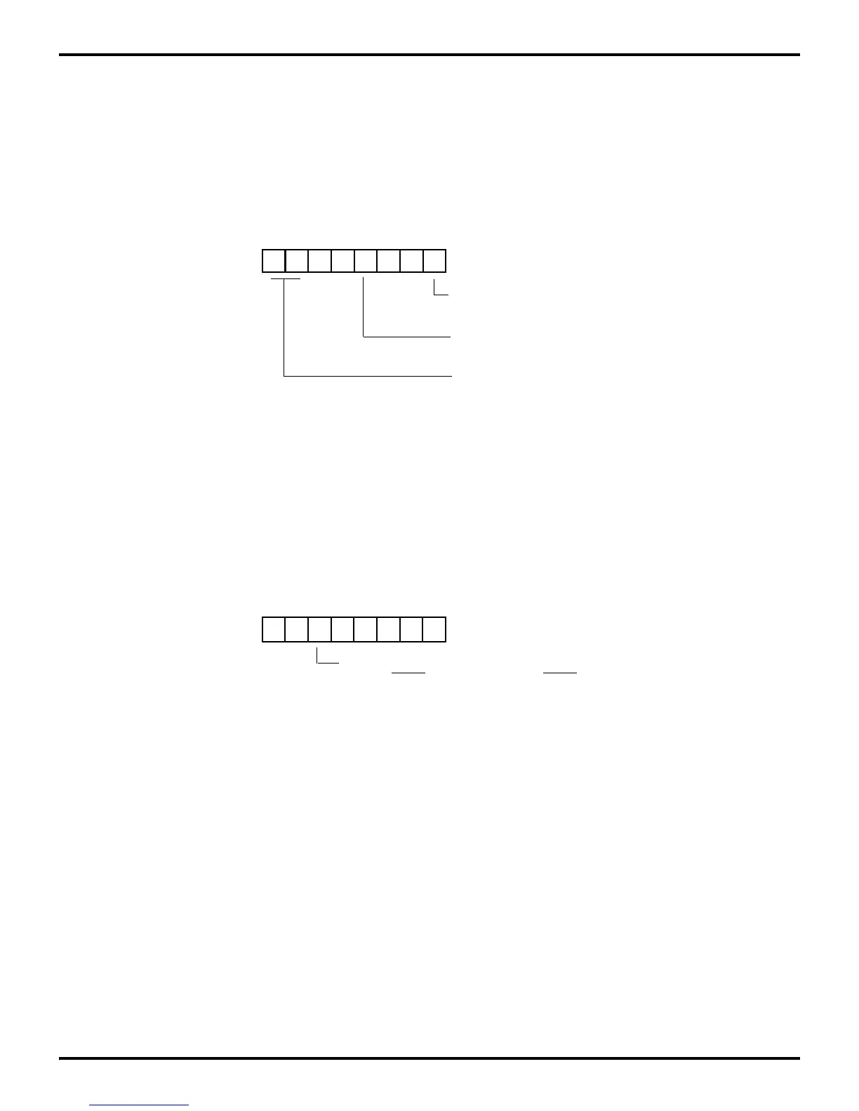
The Timer Mode Register TMR (F1H) (Figure 6-9), is used in
conjunction with the Port 3 Mode Register P3M (F7H) (Figure
6-10) to configure P36 for T
OUT
operation for T0 and T1. In or-
der for T
OUT
to function, P36 must be defined as an output line
by setting P3M bit 5 to 0. Output is controlled by one of the
counter/timers (T0 or T1) or the internal clock.
Figure 6-9. Timer Mode Register (T
OUT
Operation)
D7 D6 D3 D0
(Read/Write)
0 = No Function
1 = Load T
0
Timer Mode Register (TMR)
Register F1HR
T
OUT
Modes:
0 = Disable T
1
Count
1 = Enable T
1
Count
T
OUT
OFF = 00
T
0
OUT = 01
T
1
OUT = 10
Internal Clock OUT = 11
Figure 6-10. Port 3 Mode Register (T
OUT
Operation)
D7 D6 D5 D4 D3 D2 D1 D0
(Write-Only)
Port 3 Mode Register (P3M)
Register F7H
0 P31 = Input (T
IN
) P36 = Output (T
OUT
)
1 P31 = DAV2
/RDY2 P36 = RDY2/DAV2
 Loading...

