Z8 Microcontrollers
Counter/Timers ZiLOG
6-6 UM001601-0803
6.4 T
OUT
MODES (Continued)
The counter/timer to be output is selected by TMR bit 7 and bit
6. T0 is selected to drive the T
OUT
line by setting bit 7 to 0 and
bit 6 to 1. Likewise, T1 is selected by setting bit 7 and bit 6 to 1
and 0, respectively. The counter/timer T
OUT
mode is turned off
by setting TMR bit and bit 6 both to 0, freeing P36 to be a data
output line.
T
OUT
is initialized to a logic 1 whenever the TMR Load bit (bit
0 for T0 or bit 1 for T2) is set to 1. The T
OUT
configuration timer
load, and Timer Enable Count bits for the counter/timer driving
the T
OUT
pin can be set at the same time. For example, using the
instruction:
OR TMR,#43H
• Configures T0 to drive the T
OUT
pin (P36).
• Sets the P36 T
OUT
pin to a logic 1 level.
• Loads the initial PRE0 and T0 levels into their respective
counters and starts the counter after the M2T2 machine state
after the operand is fetched.
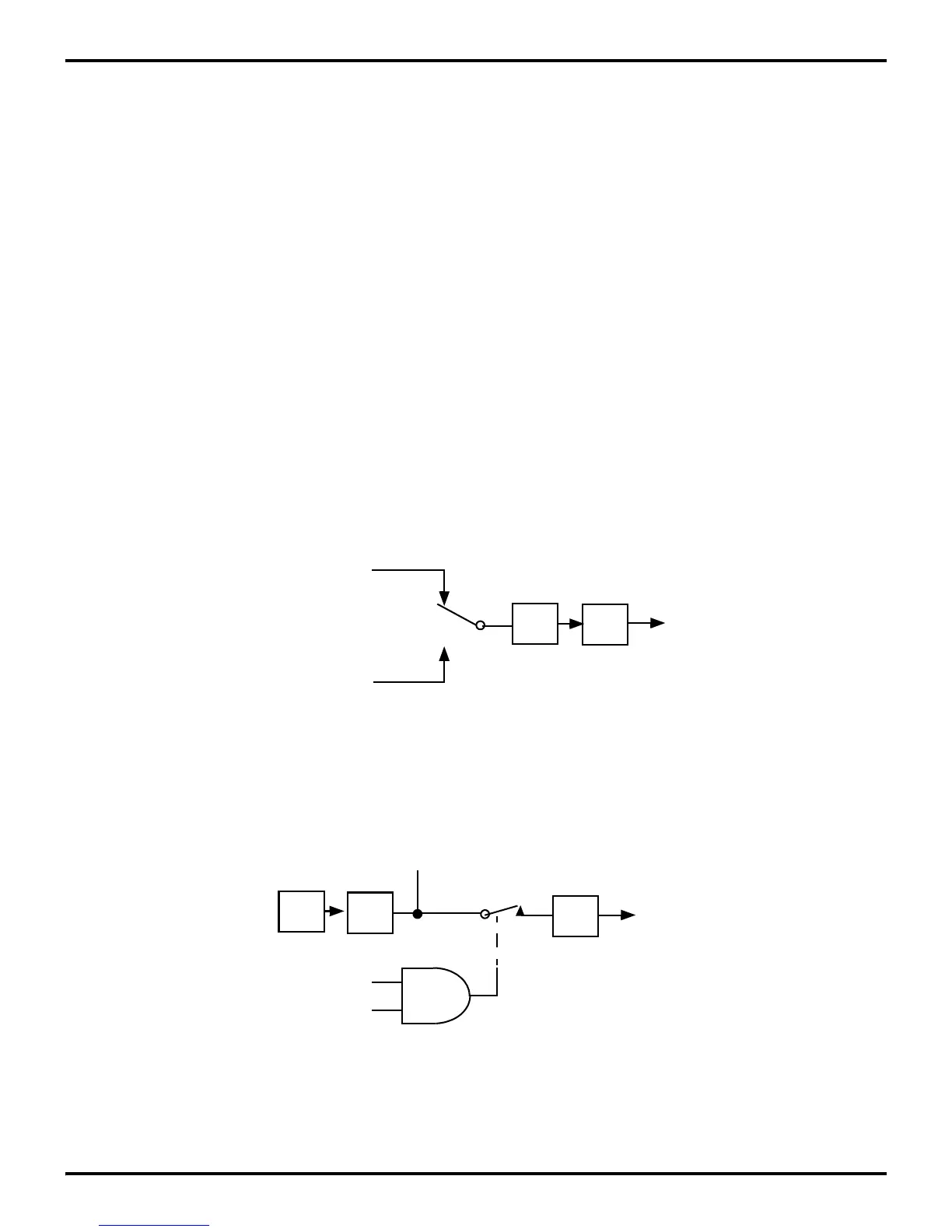
At end-of-count, the interrupt request line (IRQ4 or IRQ5),
clocks a toggle flip-flop. The output of this flip-flop drives the
T
OUT
line, P36. In all cases, when the selected counter/timer
reaches its end-of-count, T
OUT
toggles to its opposite state (Fig-
ure 6-11). If, for example, the counter/timer is in Continuous
Counting Mode, Tout will have a 50 percent duty cycle output.
This duty cycle can easily be controlled by varying the initial
values after each end-of-count.
The internal clock can be selected as output instead of T0 or T1
by setting TMR bit 7 and bit 6 both to 1. The internal clock
(XTAL frequency/2) is then directly output on P36 (Figure 6-
12).
While programmed as T
OUT
, P36 cannot be modified by a write
to port register P3. However, the Z8
®
software can examine the
P36 current output by reading the port register.
Figure 6-11. T0 and T1 Output Through T
OUT
÷2
P3
6
T
OUT
TMR
D
7
- D
6
= 01
IRQ
4
(T0 End-of-Count)
IRQ
5
(T1 End-of-Count)
TMR
D
7
- D
6
= 10
Figure 6-12. Internal Clock Output Through T
OUT
OSC
÷2
P3
6
T
OUT
Internal
TMR D
6
Clock
TMR D
7

 Loading...
