Z8 Microcontrollers
ZiLOG Interrupts
UM001601-0803 7-3
When the Port 3 pin (P31, P32, or P33) transitions, the first flip-
flop is set. The next two flip-flops synchronize the request to the
internal clock and delay it by two internal clock periods. The
output of the last flip-flop (IRQ0, IRQ1, or IRQ2) goes to the
corresponding Interrupt Request Register.
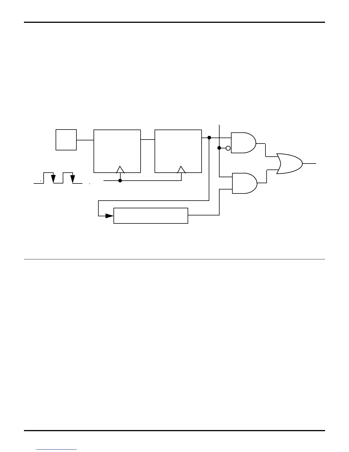
IRQ3 can be generated from an external source only if Serial In
is not enabled. Otherwise, its source is internal. The external re
-
quest is generated by a Low edge signal on P30 as shown in Fig-
ure 7-4. Again, the external request is synchronized and delayed
before reaching IRQ3. Some Z8 products replace P30 with P32
as the external source for IRQ3. In this case, IRQ3 interrupt gen
-
eration follows the logic as illustrated in Figure 7-3.
Note: Although interrupts are edge triggered, minimum
interrupt request Low and High times must be observed for
proper operation. See the device product specification for exact
timing requirements on external interrupt requests (T
W
IL,
T
W
IH).
7.2.2 Internal Interrupt Sources
Internal sources involve interrupt requests IRQ0, IRQ2, IRQ3,
IRQ4, and IRQ5. Internal sources are ORed with the external
sources, so either an internal or external source can trigger the
interrupt. Internal interrupt sources and trigger conditions are
device dependent.
See the device product specification to determine available
sources, triggering edge options, and exact programming details.
For more details on the internal interrupt sources, refer to the
chapters describing the Counter/Timer, I/O ports, and Serial I/O.
Figure 7-4. Interrupt Source IRQ3 Block Diagram
Q
PIN
D
Serial Receiver
P3M
6
IRQ
3
Clock
IRQ
3
IRQ
3
External Source
(IRQ
3
Serial In)
Internal Source
D
Q